HVAC Load Calculation Guide (Cooling & Heating)
HVAC load calculation is the most important step in HVAC system design. Accurate cooling and heating load calculations ensure correct equipment sizing, energy efficiency, and indoor comfort. This detailed guide explains HVAC load calculations step by step, covering external loads, internal loads, ventilation loads, heating losses, and industry-standard methods used by HVAC engineers worldwide.
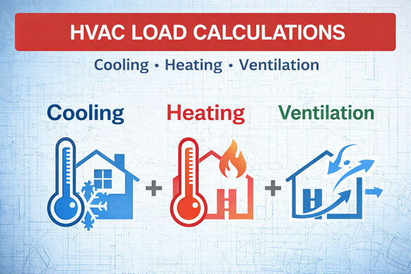
What Is HVAC Load Calculation?
HVAC load calculation is the process of estimating the total amount of heat that must be removed or added to a building to maintain indoor design conditions. It forms the basis for sizing HVAC systems for air conditioning and heating equipment.
A complete building heat load calculation includes:
- Sensible heat load (temperature change)
- Latent heat load (moisture removal)
- Ventilation and infiltration air loads
- Transmission losses during heating
External Cooling Loads
External loads are heat gains that enter the building from outdoors through walls, roofs, windows, and air leakage.
1. Wall and Roof Heat Transfer (Conduction Load)
Q = U × A × CLTDcorr
Where:
- U = Overall heat transfer coefficient (Btu/h·ft²·°F)
- A = Surface area (ft²)
- CLTDcorr = Corrected Cooling Load Temperature Difference (°F)
The CLTD/CLF method accounts for solar exposure, wall orientation, roof color, latitude, and time of year.
2. Window Heat Gain – Conduction
Q = U × A × CLTDglass
For a quick estimate, (To − Ti) can be used in place of CLTDglass. Window U-values are taken from NFRC ratings or manufacturer data. High-performance glazing significantly reduces HVAC cooling load.
3. Window Solar Heat Gain
Q = A × SC × SCL
Where:
- A = Glass area (ft²)
- SC = Shading coefficient of the glass and shading device (SC ≈ SHGC / 0.87)
- SCL = Solar Cooling Load factor for the orientation and hour (Btu/h·ft²)
Solar heat gain through windows is often the largest contributor to cooling load in commercial buildings.
Infiltration Heat Gain
Infiltration occurs due to uncontrolled outdoor air entering the building. It adds both sensible and latent heat loads.
Sensible Load:
Qs = 1.08 × CFM × ΔT
Latent Load:
Ql = 0.68 × CFM × ΔW
Where ΔT is in °F and ΔW is the humidity ratio difference in grains of moisture per lb of dry air. CFM can be calculated using the crack method or air changes per hour (ACH).
Internal Cooling Loads
Occupant (People) Heat Load
Occupants generate both sensible and latent heat.
Qs = N × qs × CLF
Ql = N × ql
Typical ASHRAE values per person:
- Seated at rest (theater): 245 Btu/h sensible, 105 Btu/h latent
- Seated, very light work (office): 245 Btu/h sensible, 155 Btu/h latent
- Moderately active office work: 250 Btu/h sensible, 200 Btu/h latent
- Standing, light work or walking: 250 Btu/h sensible, 250 Btu/h latent
Lighting Load Calculation
Q = W × 3.41 × Fu × Fsa × CLF
Where W is installed lighting power in watts, Fu is the use factor and Fsa is the special allowance factor for ballasts and drivers. LED lighting produces lower heat gain compared to fluorescent lighting.
Equipment and Appliance Load
Q = W × 3.41 × Fu × Fr × CLF
Where W is the equipment input power in watts, Fu is the usage factor and Fr is the radiation factor.
Motor heat gain, when both the motor and the driven equipment are inside the space:
Q = 2545 × (HP / Em) × FUM × FLM
Where Em is motor efficiency, FUM is the motor use factor and FLM is the motor load factor. Manufacturer data should always be used where available.
Ventilation Load Calculation (ASHRAE 62.1)
Ventilation load is calculated based on required outdoor air as per ASHRAE Standard 62.1.
Vbz = Rp × Pz + Ra × Az
Voz = Vbz / Ez
Where Rp is outdoor air per person, Pz is zone population, Ra is outdoor air per unit area, Az is zone floor area and Ez is the zone air distribution effectiveness. For a ready-made spreadsheet, see the ASHRAE Ventilation Calculation XLS.
Sensible Ventilation Load:
Qs = 1.08 × CFM × (To − Ti)
Latent Ventilation Load:
Ql = 0.68 × CFM × (Wo − Wi)
Where Wo and Wi are outdoor and indoor humidity ratios in grains/lb. These can be read from a psychrometric chart; see Psychrometric Processes in HVAC.
Duct Heat Gain and Safety Factor
Duct heat gain or loss must be considered when ducts pass through unconditioned spaces.
Q = Uduct × Aduct × ΔT
A HVAC safety factor of 10–20% is commonly added to account for uncertainties, future equipment, and distribution losses. Avoid stacking safety factors at every step, as this leads to oversized equipment.
Heating Load Calculation
Transmission Heat Loss
Q = U × A × (Ti − To)
Infiltration Heat Loss
Q = 1.08 × CFM × (Ti − To)
Basement and Slab Heat Loss
Q = F × P × (Ti − To)
Where F is the slab edge heat loss coefficient (Btu/h·ft·°F) and P is the exposed slab perimeter (ft). Additional pickup load of 10–40% is applied for morning warm-up and building thermal mass.
Total HVAC Load Summary
Qtotal = Qsensible + Qlatent
Cooling Capacity (TR) = Qtotal (Btu/h) / 12,000
Diversity factors are applied since all loads do not peak simultaneously. For quick conversions between tons, CFM and kW, see the AC Tonnage Chart.
Once the total load is known, the next decision is which system will carry it. Our guide to the types of HVAC systems compares split, ducted, packaged, VRF, chilled water and district cooling systems, with animated diagrams of how each one works.
HVAC Load Calculation Standards and Methods
- RTS Method (Radiant Time Series), the current ASHRAE method
- CLTD / SCL / CLF Method, used in this guide for hand calculations
- Transfer Function Method (TFM)
- Manual J (Residential Load Calculation)
For large projects, software such as Carrier HAP (Hourly Analysis Program) runs these calculations hour by hour for every zone.
Related HVAC Tools on MEPBase
- Cooling Load Calculator
- Room Heat Load Calculator
- E20 Heat Load Calculator
- Psychrometric Calculator
- Online Ductulator
- Chilled Water Pipe Calculator
- AC Condensate Drain Calculator
- HVAC Unit Converter
HVAC Design Calculations Series
Once the cooling load is known, these step-by-step guides take you through the rest of the system design:
- External Static Pressure (ESP) Calculation for AHU and FCU
- Chilled Water Pump Head Calculation
- Expansion Tank Sizing for Chilled Water Systems
- VAV Box Sizing and Selection
- Kitchen Hood CFM Calculation and Grease Duct Sizing
- Refrigerant Pipe Sizing for VRF and Split Systems
- Cooling Tower Sizing
- Smoke Exhaust Calculation for Atriums
- Cooling Coil Selection
- Fan Laws and VFD Energy Savings
Conclusion
A proper HVAC load calculation is essential for efficient HVAC design. By correctly estimating cooling and heating loads using ASHRAE methods, engineers can select optimal equipment capacity, reduce energy consumption, and ensure long-term system reliability.