Cooling Coil Selection: ADP, Bypass Factor, Rows and Face Velocity Explained
A coil that matches the total load on paper can still leave a room humid if it can’t reach the right leaving air condition. This guide walks through cooling coil selection step by step: coil load from entering and leaving air, apparatus dew point (ADP), bypass factor and rows, face velocity, chilled water flow and condensate, with a full worked example for a 10,000 CFM AHU.
What goes into a cooling coil selection
A chilled water coil has to do two jobs at once: lower the air temperature (sensible cooling) and remove moisture (latent cooling). Manufacturers select the final coil in their software, but the designer has to give them the right inputs and check that the result makes sense. This guide focuses on those inputs. For the psychrometric theory behind them, see Psychrometric Processes in HVAC.
Step 1: Calculate the coil load
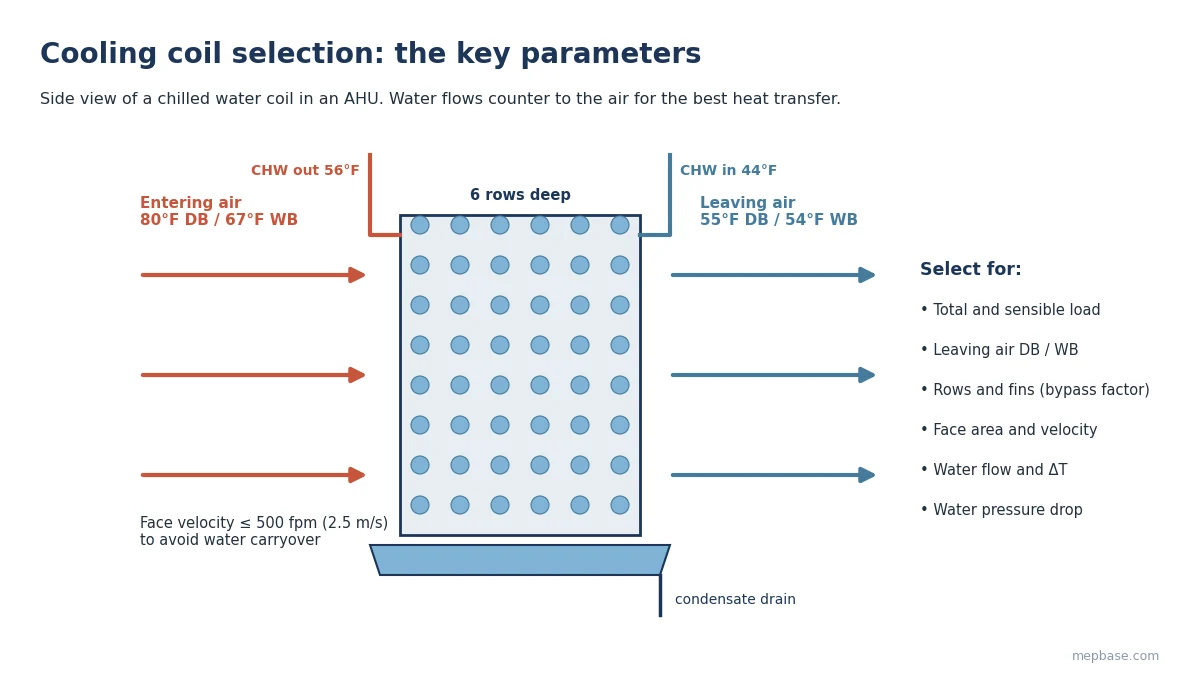
Coil load comes from the airflow and the change in air condition across the coil, not from the room load alone, because it also includes outdoor air and fan heat:
Total load (Btu/h) = 4.5 × CFM × (hentering − hleaving), with enthalpy h in Btu/lb
Sensible load (Btu/h) = 1.08 × CFM × (Tentering − Tleaving)
Sensible heat ratio (SHR) = Sensible load / Total load
In SI: Total load (kW) = 1.2 × airflow (m³/s) × Δh (kJ/kg), and Sensible load (kW) = 1.21 × airflow (m³/s) × ΔT (K). Read enthalpies from a psychrometric chart or the Psychrometric Calculator. The entering condition is usually the mixed air (return plus outdoor air) at the coil face.
Step 2: Set the leaving air condition and find the ADP
The leaving air condition must satisfy both the room sensible load and the room latent load. For comfort cooling, 55°F DB / 54°F WB (12.8°C / 12.2°C) is a common starting point; spaces with high latent loads may need lower.
On the psychrometric chart, the coil process is a straight line from the entering state through the leaving state. Extend it until it meets the saturation curve: that point is the apparatus dew point (ADP), the effective surface temperature of the coil.
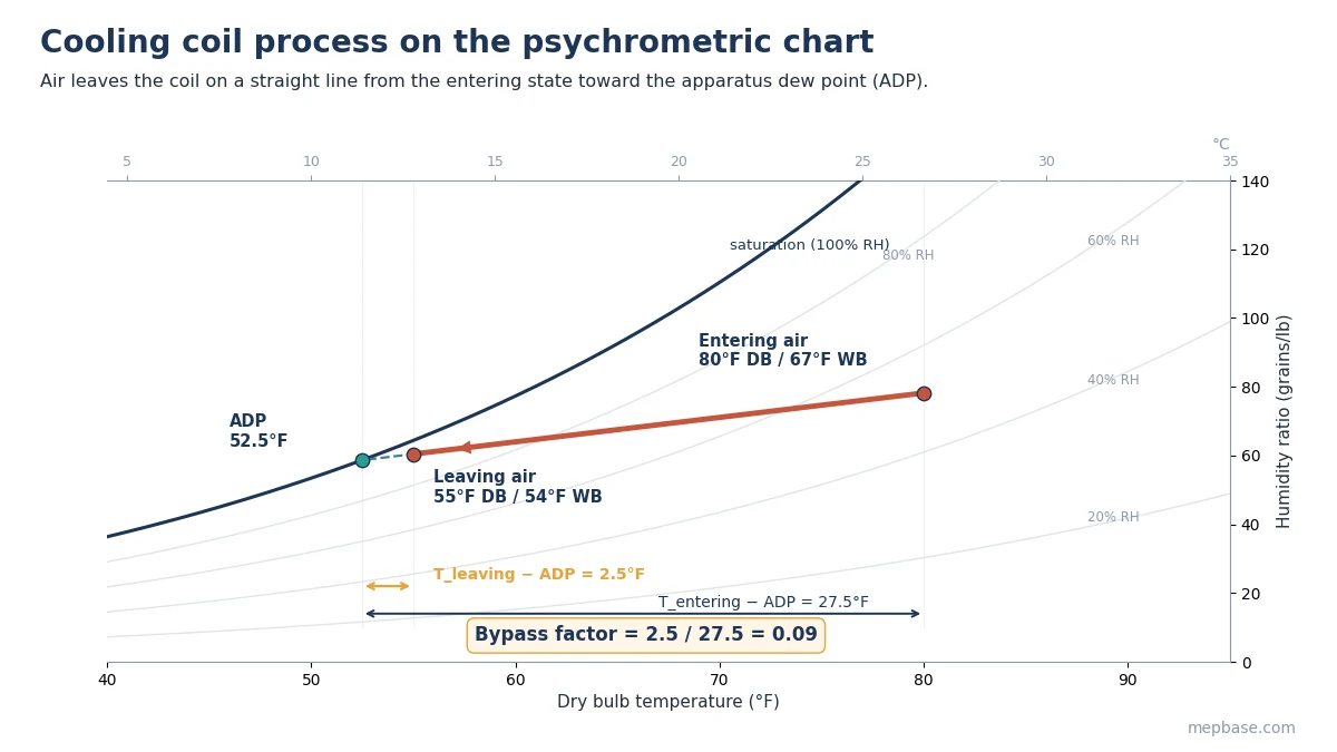
If the line never reaches the saturation curve, or the ADP is below about 45°F (7°C), the leaving condition is not achievable with normal chilled water and needs another look. A printable chart is available in the Psychrometric Chart PDF.
Step 3: Calculate the bypass factor and choose the rows
Not all air touches the cold coil surface. The bypass factor (BF) describes the share that effectively passes through untreated:
BF = (Tleaving − ADP) / (Tentering − ADP)
Contact factor = 1 − BF
A lower bypass factor needs a deeper coil (more rows), more fins per inch, or a lower face velocity. Typical values for plate-fin coils at about 500 fpm:
| Rows | Bypass factor, 8 fins/in | Bypass factor, 14 fins/in |
|---|---|---|
| 2 | 0.55 | 0.38 |
| 3 | 0.40 | 0.23 |
| 4 | 0.30 | 0.14 |
| 5 | 0.22 | 0.09 |
| 6 | 0.16 | 0.06 |
| 8 | 0.09 | 0.02 |
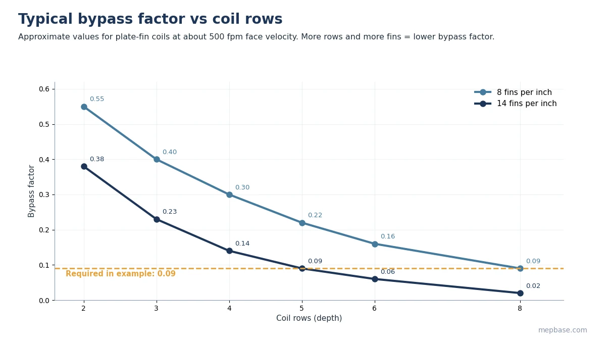
These are approximate figures for preliminary selection. Chilled water comfort coils are usually 4 to 8 rows; more rows add air pressure drop, so check the fan’s static pressure too.
Step 4: Size the face area
Face area (ft²) = CFM / Face velocity (fpm)
Keep face velocity at or below about 500 fpm (2.5 m/s). Above that, condensate can be blown off the fins and carried into the ductwork. Many designers use 400 to 500 fpm (2.0 to 2.5 m/s), which also keeps the coil’s air pressure drop reasonable.
Step 5: Set chilled water flow and temperature difference
Water flow (GPM) = Total load (Btu/h) / (500 × Water ΔT (°F))
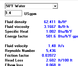
Chilled water is commonly supplied at 42 to 45°F (5.5 to 7°C) with a 10 to 16°F (5.5 to 9 K) temperature rise. A larger ΔT cuts pumping energy but needs a deeper coil. Keep tube water velocity at roughly 2 to 6 fps (0.6 to 1.8 m/s), and give the coil’s water pressure drop to the pump designer; see Chilled Water Pump Head Calculation. You can check flows with the Chilled Water Flow Calculator.
Step 6: Estimate condensate
Condensate (lb/h) = 4.5 × CFM × (Wentering − Wleaving) / 7,000, with W in grains/lb
Divide by 8.34 for US gallons per hour. Use this to size the drain pan connection and condensate piping; see the AC Condensate Drain Calculator or the AC Condensate Drain Calculator Excel.
Cooling coil selection: worked example for a 10,000 CFM AHU
An AHU handles 10,000 CFM (4,720 L/s) of mixed air entering the coil at 80°F DB / 67°F WB. The required leaving condition is 55°F DB / 54°F WB. Chilled water is supplied at 44°F with a 12°F rise.
| Step | Calculation | Result |
|---|---|---|
| Entering air | 80°F DB / 67°F WB | h = 31.45 Btu/lb, W = 78.2 gr/lb |
| Leaving air | 55°F DB / 54°F WB | h = 22.57 Btu/lb, W = 60.4 gr/lb |
| Total load | 4.5 × 10,000 × (31.45 − 22.57) | 399,600 Btu/h (33.3 TR, 117 kW) |
| Sensible load | 1.08 × 10,000 × (80 − 55) | 270,000 Btu/h (79 kW) |
| SHR | 270,000 / 399,600 | 0.68 |
| ADP | process line to saturation | 52.5°F (11.4°C) |
| Bypass factor | (55 − 52.5) / (80 − 52.5) | 0.09 |
| Rows | from bypass factor table | 5 rows at 14 fins/in; select 6 rows for margin |
| Face area at 500 fpm | 10,000 / 500 | 20 ft² minimum; use 22 ft² (455 fpm) |
| Chilled water flow | 399,600 / (500 × 12) | 66.6 GPM (4.2 L/s) |
| Condensate | 4.5 × 10,000 × (78.2 − 60.4) / 7,000 | 114 lb/h (13.7 GPH, 52 L/h) |
These figures go to the manufacturer as the selection basis: 10,000 CFM, 80/67°F entering, 55/54°F leaving, 44°F CHW with a 12°F rise, maximum 500 fpm face velocity. Check their selection against the rows, water pressure drop and air pressure drop above. Try your own numbers in the Cooling Coil Calculator.
Common mistakes
- Selecting the coil on room load instead of the full coil load including outdoor air.
- Specifying only total capacity, so the coil meets tons but misses the latent load.
- Asking for a leaving condition whose ADP is lower than the chilled water can reach.
- Pushing face velocity above 500 fpm and getting water carryover into the ductwork.
- Forgetting that extra rows add air pressure drop, which the fan must overcome.
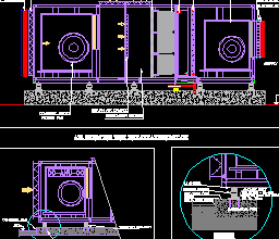
For AHU coil and drain pan installation details, see the Air Handling Unit Installation Detail DWG.
Frequently asked questions
What is apparatus dew point (ADP)?
It is the effective surface temperature of the cooling coil, found where the coil process line meets the saturation curve on the psychrometric chart.
What is a good bypass factor for a cooling coil?
For comfort cooling with chilled water, about 0.05 to 0.15. Lower values need more rows or more fins.
What face velocity should a cooling coil have?
At or below about 500 fpm (2.5 m/s) to prevent condensate carryover. 400 to 500 fpm is common.
How many rows should a chilled water coil have?
Most comfort coils have 4 to 8 rows. The required number comes from the bypass factor needed to reach the leaving air condition.