Expansion Tank Sizing for Chilled Water Systems: Formula and Worked Example
An undersized expansion tank makes the relief valve lift every time the plant shuts down; one connected in the wrong place can pull air into the system. This guide covers expansion tank sizing for closed chilled water systems step by step: system volume, temperature range, fill and maximum pressures, and the ASHRAE formula, with a full worked example.
What the expansion tank does
Water expands as it warms. In a closed chilled water system, the water is at its coldest while the plant runs and warms toward ambient when the plant is off. Without somewhere to go, that expansion raises system pressure until the relief valve lifts. The expansion tank absorbs it and also sets the system’s fill pressure at its connection point.
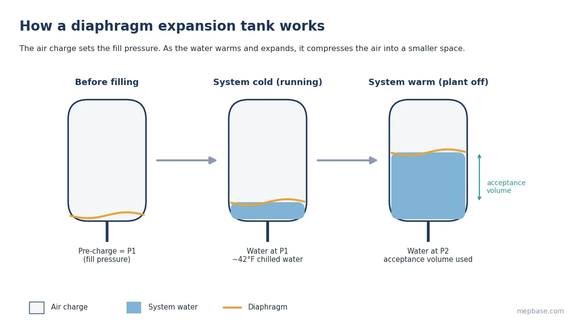
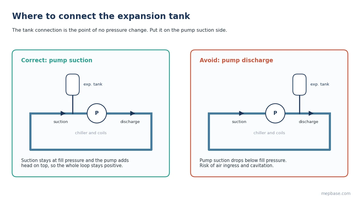
The tank connection is the point of no pressure change in the system, so connect it on the suction side of the chilled water pumps.
Step 1: Estimate the system water volume
Add up the water in pipes, chillers, coils and buffer tanks. For pipes, multiply length by water content per foot:
| Pipe size (Sch 40) | Water content (gal/ft) | Water content (L/m) |
|---|---|---|
| 2 in (DN50) | 0.17 | 2.2 |
| 3 in (DN80) | 0.38 | 4.8 |
| 4 in (DN100) | 0.66 | 8.2 |
| 6 in (DN150) | 1.50 | 18.6 |
| 8 in (DN200) | 2.60 | 32.3 |
| 10 in (DN250) | 4.10 | 50.9 |
Take chiller evaporator and coil volumes from manufacturer data. Add 10% for anything you haven’t counted. Pipe dimensions for other schedules are in the Pipe Schedule Reference.
Step 2: Define the temperature range
Use the lowest temperature the water will reach (chilled water supply, typically 42 to 44°F / 5.5 to 7°C) and the highest it will reach with the plant off. In a plant room or in exposed pipework, that can be 95 to 110°F (35 to 43°C). Pick a realistic maximum for the site; it controls how much the water expands.
Step 3: Set the minimum and maximum pressures at the tank
Minimum pressure (P1) is the fill or pre-charge pressure. It must keep the highest point of the system positive:
P1 = Static height above the tank (ft) / 2.31 + 4 to 5 psi
Maximum pressure (P2) is the highest pressure allowed at the tank. It must stay below the relief valve setting and below the pressure rating of the weakest component at the lowest point of the system. Keep P2 at least 10% below the relief valve setting. Also check the running condition: P1 plus pump head at the pump discharge must stay below equipment ratings too.
Use absolute pressures in the formula: psia = psig + 14.7 (kPa abs = kPa g + 101.3).
Step 4: Apply the ASHRAE formula for a diaphragm tank
Vt = Vs × [(v2 / v1 − 1) − 3α × ΔT] / (1 − P1 / P2)
Where Vt is total tank volume, Vs is system volume, v1 and v2 are the specific volumes of water at the minimum and maximum temperatures, α is the linear expansion coefficient of the pipe (6.5 × 10⁻⁶ per °F for steel, 11.7 × 10⁻⁶ per °C), and ΔT is the temperature range.
The 3αΔT term accounts for the pipework itself expanding and making a little extra room. For copper or plastic pipe, use the matching coefficient.
Select a tank whose acceptance volume is at least Vs × [(v2 / v1 − 1) − 3αΔT], and whose total volume is at least Vt.
Expansion tank sizing: worked example for a 3,000 gal system
A chilled water system holds 3,000 gal (11,356 L). The tank sits at the pump suction in a basement plant room. The highest pipe is 100 ft (30.5 m) above the tank. Water ranges from 42°F (5.6°C) running to 100°F (37.8°C) with the plant off. Relief valve setting is 100 psig.
| Step | Calculation | Result |
|---|---|---|
| Water expansion | v at 100°F / v at 42°F − 1 | 0.0070 |
| Pipe expansion | 3 × 6.5 × 10⁻⁶ × 58 | 0.0011 |
| Net expansion factor | 0.0070 − 0.0011 | 0.0059 |
| Acceptance volume | 3,000 × 0.0059 | 17.7 gal (67 L) |
| P1 (fill) | 100 / 2.31 + 5 = 48.3 psig | 63.0 psia |
| P2 (max) | 90 psig (10% below relief) | 104.7 psia |
| Pressure factor | 1 − 63.0 / 104.7 | 0.398 |
| Tank volume | 17.7 / 0.398 | 44.5 gal, select 50 gal (190 L) |
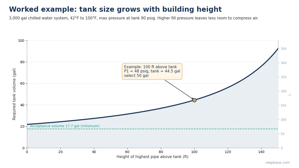
Set the tank pre-charge to 48 psig (331 kPa g) before filling the system. Run your own numbers in the Expansion Tank Calculator.
Compression (plain steel) tanks
Older systems use plain steel tanks where air and water touch. They need a much larger tank for the same system because the air cushion starts at atmospheric pressure. The ASHRAE formula changes to:
Vt = Vs × [(v2 / v1 − 1) − 3α × ΔT] / (Pa / P1 − Pa / P2)
Where Pa is atmospheric pressure (absolute). Diaphragm or bladder tanks are the normal choice in new chilled water systems.
Common mistakes
- Connecting the tank on the pump discharge, which can drop suction pressure and cause cavitation.
- Using gauge pressures in the formula instead of absolute.
- Leaving the factory pre-charge (often 12 psig) instead of setting it to the calculated fill pressure.
- Ignoring buffer tanks and large coils when estimating system volume.
- Choosing too narrow a temperature range for a plant that sits idle in hot weather.
The tank’s connection point also affects pump suction pressure, so read this together with Chilled Water Pump Head Calculation. For pipe sizing on the same system, see Chilled Water Pipe Sizing.
Frequently asked questions
Where should the expansion tank be connected?
On the suction side of the chilled water pumps, close to the pumps, so pump head adds to system pressure rather than reducing it.
How much does chilled water expand?
About 0.7% between 42°F and 100°F. Pipe expansion offsets a small part of that.
What should the tank pre-charge pressure be?
Equal to the calculated minimum fill pressure at the tank, set before the system is filled.
Can one tank serve multiple chillers?
Yes, if the chillers share one hydraulic system. Size it on the total system volume.