Smoke Exhaust Calculation for Atriums: NFPA 92 Plume Method Step by Step
In an atrium fire, smoke rises fast and fills the space from the top down. A properly sized exhaust system holds the smoke above people’s heads long enough for them to get out. This guide walks through the smoke exhaust calculation for atriums and large spaces using the NFPA 92 axisymmetric plume method: design fire, smoke layer height, plume mass flow, exhaust volume, plugholing and make-up air, with a full worked example.
What a smoke exhaust system does
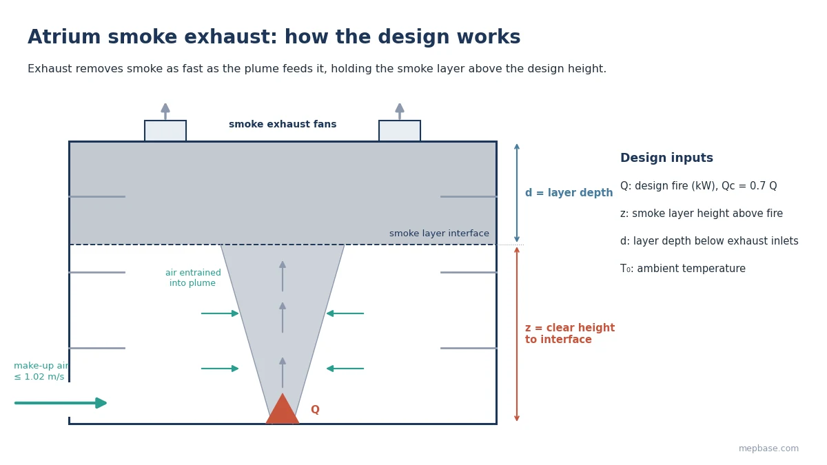
A fire produces hot smoke that rises as a plume. On the way up, the plume pulls in (entrains) large amounts of surrounding air, so the mass of smoke reaching the ceiling is far greater than what the fire itself produces. The smoke collects under the roof as a layer that gets deeper over time.
A steady-state smoke exhaust system removes smoke at the same rate the plume delivers it to the layer. The smoke layer interface then stays at a fixed height. A common design criterion is to keep the interface at least 1.83 m (6 ft) above the highest walking surface that must stay tenable during evacuation.
Step 1: Choose the design fire
The design fire is the steady heat release rate (Q) the system is designed for. It depends on the fuel likely to be present on the atrium floor and whether sprinklers will control the fire. Typical values used in practice:
| Space | Typical design fire |
|---|---|
| Sprinklered atrium with limited combustibles | 2.5 MW (2,500 kW) |
| Atrium with some furniture, kiosks or planters | 5 MW (5,000 kW) |
| Retail, exhibition or storage areas open to the atrium | Higher, set by fire engineering analysis |
Only part of the fire’s heat goes into the plume as convection; the rest is radiated. NFPA 92 uses:
Qc = 0.7 × Q
Step 2: Set the design smoke layer height
The clear height z is measured from the base of the fire to the smoke layer interface. Set it from the tenability criterion above, then check that the remaining smoke layer depth below the roof is enough for the exhaust inlets (see Step 5).
Step 3: Calculate the plume mass flow
First find the limiting flame height:
zl = 0.166 × Qc2/5 (m, with Qc in kW)
If the smoke layer is above the flames (z > zl), which is the normal design case:
m = 0.071 × Qc1/3 × z5/3 + 0.0018 × Qc (kg/s)
If the smoke layer would be within the flames (z ≤ zl):
m = 0.032 × Qc3/5 × z (kg/s)
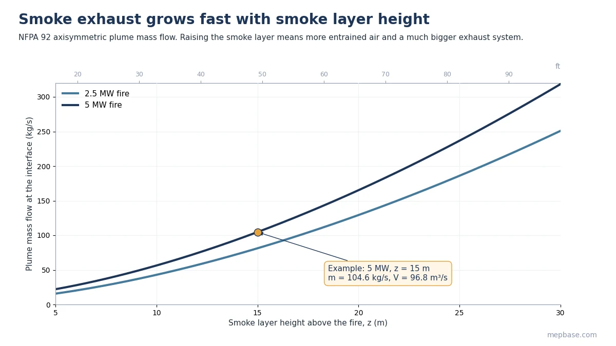
Because of the z5/3 term, the required exhaust grows quickly as the smoke layer is raised. Raising the clear height from 10 m to 20 m roughly triples the mass flow.
Step 4: Convert to exhaust volume
Smoke is hotter and lighter than ambient air, so the fan must move a larger volume than the mass flow suggests. Assuming all convective heat stays in the smoke (a conservative assumption for the volume):
Smoke temperature rise ΔT = Qc / (m × cp), with cp = 1.0 kJ/kg·K
Smoke density ρ = 353 / Ts (kg/m³, Ts in kelvin)
Exhaust volume V = m / ρ (m³/s)
Step 5: Check plugholing
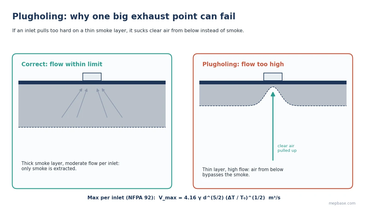
If a single exhaust inlet pulls too hard on the smoke layer, it draws clear air up through the layer instead of smoke. This is called plugholing, and it limits how much each inlet can extract:
Vmax = 4.16 × γ × d5/2 × (ΔT / T0)1/2 (m³/s per inlet)
Where d is the depth of the smoke layer below the inlet (m), ΔT is the smoke temperature rise (K), T0 is the ambient temperature (K), and γ is 1.0 for inlets well away from walls and 0.5 for inlets close to a wall. The minimum number of inlets is V / Vmax, rounded up.
Step 6: Provide make-up air
Air removed by the exhaust must be replaced at low level, below the smoke layer. Typical practice:
- Supply make-up air at about 85 to 95% of the exhaust volume, so the space stays slightly negative and smoke does not spread into adjoining areas.
- Keep make-up air velocity at no more than 1.02 m/s (200 fpm) where it can reach the plume or the fire, so it does not deflect the plume or disturb the smoke layer.
- Use doors, louvres or dedicated fans that open automatically on alarm.
Smoke exhaust calculation: worked example for a 5 MW atrium fire
An atrium is 25 m high. The design fire is 5 MW at floor level, the ambient temperature is 20°C (293 K), and the smoke layer interface must be held at 15 m above the floor. Exhaust inlets are at the roof, well away from walls.
| Step | Calculation | Result |
|---|---|---|
| Convective heat release | 0.7 × 5,000 | Qc = 3,500 kW |
| Limiting flame height | 0.166 × 3,5000.4 | zl = 4.3 m, so z = 15 m is above the flames |
| Plume mass flow | 0.071 × 3,5001/3 × 155/3 + 0.0018 × 3,500 | m = 104.6 kg/s |
| Smoke temperature rise | 3,500 / (104.6 × 1.0) | ΔT = 33.4 K, Ts = 53°C (326 K) |
| Smoke density | 353 / 326.4 | ρ = 1.08 kg/m³ |
| Exhaust volume | 104.6 / 1.08 | V = 96.8 m³/s (about 205,000 CFM) |
| Smoke layer depth below inlets | 25 − 15 | d = 10 m |
| Plugholing limit per inlet | 4.16 × 1.0 × 102.5 × (33.4 / 293)0.5 | Vmax = 444 m³/s, so plugholing is not a concern |
| Make-up air at 90% | 0.9 × 96.8 | 87.1 m³/s |
| Make-up air opening at 1.02 m/s | 87.1 / 1.02 | at least 85 m² of free area |
Even though one inlet could handle the flow, the exhaust would normally be split across several fans for redundancy and even extraction, for example four fans of about 24.2 m³/s each. Run your own atrium in the Smoke Exhaust Calculator.
Fans, ducts and controls
- Smoke exhaust fans, dampers and ductwork must be rated for the expected smoke temperature and duration under the code that applies to the project.
- Calculate fan static pressure from the exhaust ductwork and roof discharge the same way as for any fan system; see External Static Pressure (ESP) Calculation for AHU and FCU and the Fan Static Pressure Calculator.
- Power the system from a secondary (emergency) supply and start it automatically from the fire alarm, with manual override at the fire command centre.
- Commission it with a full sequence test: alarm, fans, dampers, make-up air openings and HVAC shutdown or changeover.
When this method is not enough
The axisymmetric plume equations assume a fire on the floor of a large open space. Balcony spill plumes, window plumes, fires against walls or in corners, very tall atriums with stratification, and complex geometries need other NFPA 92 equations or a computational fluid dynamics (CFD) study. Smoke control design is life safety work, so the final design should be prepared or reviewed by a qualified fire protection engineer and approved by the authority having jurisdiction. For water-based fire protection design, see Fire Fighting System Design Calculation.
Common mistakes
- Using the total heat release instead of the convective part (Qc = 0.7 Q).
- Setting the smoke layer higher “to be safe” without realising the exhaust grows with z5/3.
- Sizing fans on mass flow instead of volume at smoke temperature.
- Putting all exhaust through one or two inlets on a shallow smoke layer and causing plugholing.
- Forgetting make-up air, or supplying it so fast that it blows the plume sideways.
Frequently asked questions
What design fire size is used for atrium smoke exhaust?
Commonly 2.5 MW for sprinklered atriums with limited fuel and 5 MW where more combustibles may be present. The final value should come from a fire engineering assessment.
Why does smoke exhaust increase with ceiling height?
The plume entrains air as it rises, so the higher the smoke layer is held, the more air is mixed into the smoke and the more must be exhausted.
What is plugholing in smoke control?
It is when an exhaust inlet pulls clear air from below the smoke layer instead of smoke, because the flow through that inlet is too high for the layer depth.
What velocity is allowed for make-up air?
NFPA 92 limits make-up air velocity to 1.02 m/s (200 fpm) where it could reach the plume, so the plume and smoke layer are not disturbed.