External Static Pressure (ESP) Calculation for AHU and FCU: Step-by-Step Guide
External static pressure (ESP) is the number you put on every AHU and FCU schedule, and getting it wrong shows up on site as warm rooms, noisy ceilings or wasted fan power. This guide walks through the external static pressure calculation step by step using the index run method, with typical component losses and a full worked example.
What is external static pressure?
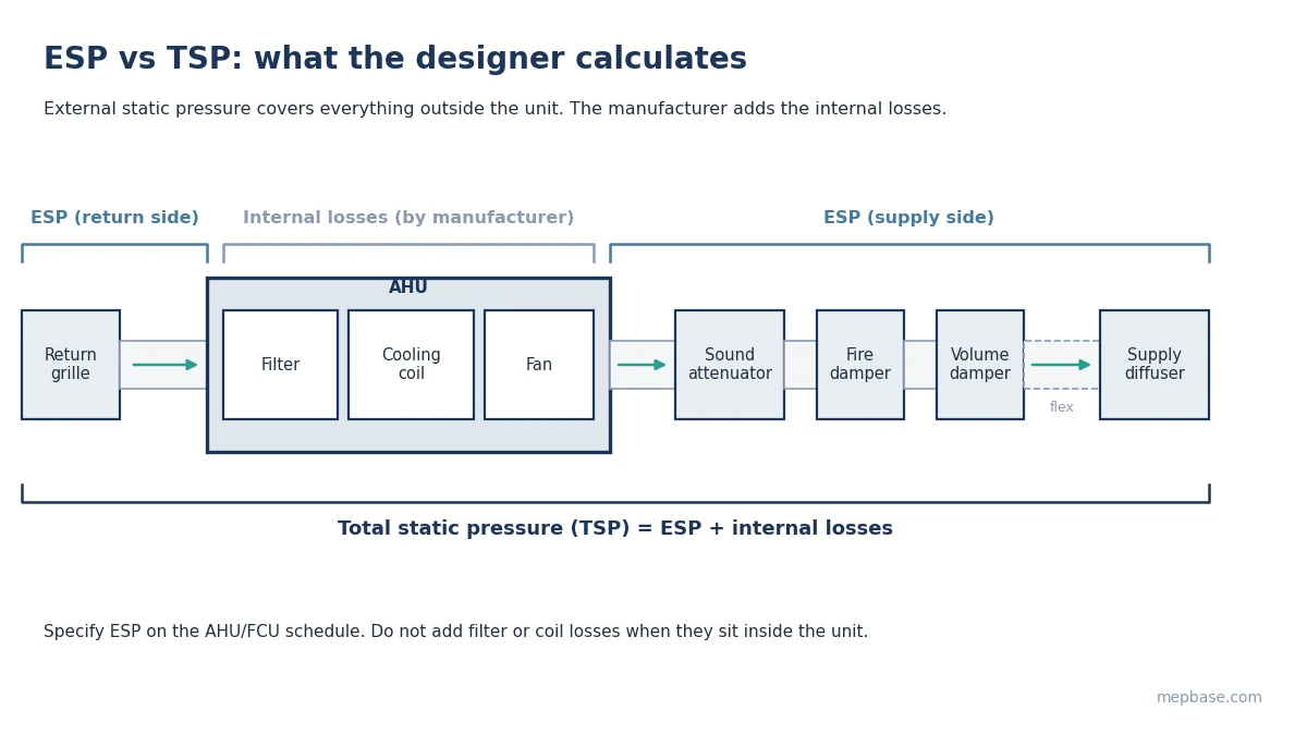
External static pressure (ESP) is the pressure the fan must develop to push air through everything outside the unit: supply ducts, return ducts, fittings, dampers, attenuators, diffusers and grilles. It is the number you put on the AHU or FCU schedule so the manufacturer can select the right fan.
ESP is not the same as total static pressure (TSP). TSP is ESP plus the internal losses of the unit itself (filters, coil, mixing box, heat recovery). Manufacturers add the internal losses; the designer provides the ESP.
Get ESP too low and the unit cannot deliver design airflow, so rooms stay warm. Get it too high and the fan runs louder, uses more power and the balancing dampers end up nearly closed.
Step 1: Find the index run
ESP is set by the single path with the highest resistance, called the index run or critical path. You do not add up every branch in the system. Usually the index run is the longest duct run with the most fittings, but a shorter run with a sound attenuator or extra dampers can sometimes be worse, so check two or three candidate runs.
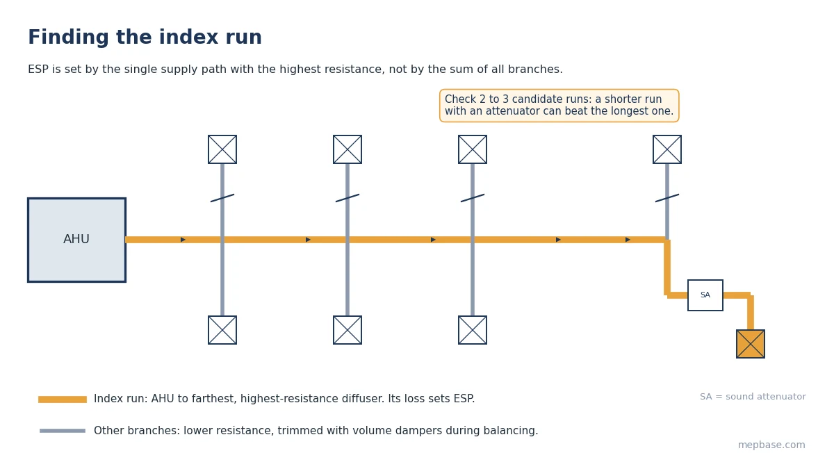
Do this separately for the supply side and the return side.
Step 2: Calculate straight duct friction loss
Multiply the length of each section by its friction rate:
Straight duct loss = Length × Friction rate / 100
For low-pressure comfort systems sized by the equal friction method, the friction rate is typically 0.08 to 0.10 in.wg per 100 ft (0.65 to 0.8 Pa/m). If you sized ducts with a ductulator, use the same friction rate here. You can check any section with the Duct Friction and Velocity Calculator. For the difference between sizing methods, see Equal Friction vs Velocity Method.
Step 3: Add fitting losses
Every elbow, tee, transition and takeoff adds a loss. The most accurate method uses the fitting loss coefficient (C) from the ASHRAE Duct Fitting Database or SMACNA tables:
Fitting loss (in.wg) = C × Velocity pressure
Velocity pressure (in.wg) = (V / 4005)², with V in fpm
In SI: Velocity pressure (Pa) = 0.6 × v², with v in m/s (standard air).
Typical C values: smooth radius elbow 0.15 to 0.25, mitred elbow without vanes about 1.2, mitred elbow with turning vanes 0.2 to 0.35, branch takeoff 0.4 to 1.0 depending on flow ratio.
Step 4: Add terminal devices and accessories
Use manufacturer data at the actual airflow wherever you have it. When you don’t, these typical values are reasonable for preliminary design:
| Component | Typical loss (in.wg) | Typical loss (Pa) |
|---|---|---|
| Supply diffuser | 0.05 to 0.10 | 12 to 25 |
| Return or exhaust grille | 0.03 to 0.05 | 7 to 12 |
| Volume control damper (open) | 0.02 to 0.05 | 5 to 12 |
| Fire damper | 0.03 to 0.05 | 7 to 12 |
| Sound attenuator | 0.10 to 0.15 | 25 to 37 |
| Flexible duct connection (short run) | 0.03 to 0.05 | 7 to 12 |
| VAV box (inlet, damper open) | 0.25 to 0.50 | 60 to 125 |
Step 5: Repeat for the return side, add a safety margin
Calculate the return index run the same way. Then:
ESP = Supply index run loss + Return index run loss + Safety margin
A 10 to 15% margin is normal. Avoid stacking margins (on friction rate, on fittings and again on the total), which is how ESP ends up double what the system needs.
External static pressure calculation: worked example for a 4,000 CFM AHU
An AHU supplies 4,000 CFM (1,888 L/s) to an office floor. Supply index run is 150 ft (46 m) with a friction rate of 0.10 in.wg/100 ft. Main duct velocity near the elbows is 1,200 fpm; branch velocity is 900 fpm. Return index run is 60 ft (18 m) at 0.08 in.wg/100 ft.
Velocity pressure at 1,200 fpm = (1200 / 4005)² = 0.090 in.wg
Velocity pressure at 900 fpm = (900 / 4005)² = 0.050 in.wg
| Item | Calculation | Loss (in.wg) |
|---|---|---|
| Supply straight duct | 150 × 0.10 / 100 | 0.150 |
| 4 smooth radius elbows | 4 × 0.25 × 0.090 | 0.090 |
| Branch takeoff | 0.50 × 0.050 | 0.025 |
| Transition | allowance | 0.010 |
| Sound attenuator | manufacturer data | 0.120 |
| Fire damper | typical | 0.040 |
| Volume damper | typical | 0.030 |
| Flexible duct to diffuser | typical | 0.050 |
| Supply diffuser | manufacturer data | 0.080 |
| Supply subtotal | 0.595 | |
| Return straight duct | 60 × 0.08 / 100 | 0.048 |
| Return fittings | allowance | 0.040 |
| Fire damper | typical | 0.040 |
| Return grille | manufacturer data | 0.040 |
| Return subtotal | 0.168 | |
| Supply + return | 0.763 | |
| Safety margin 10% | 0.763 × 0.10 | 0.076 |
| Design ESP | 0.84, specify 0.85 in.wg (approx. 212 Pa) |
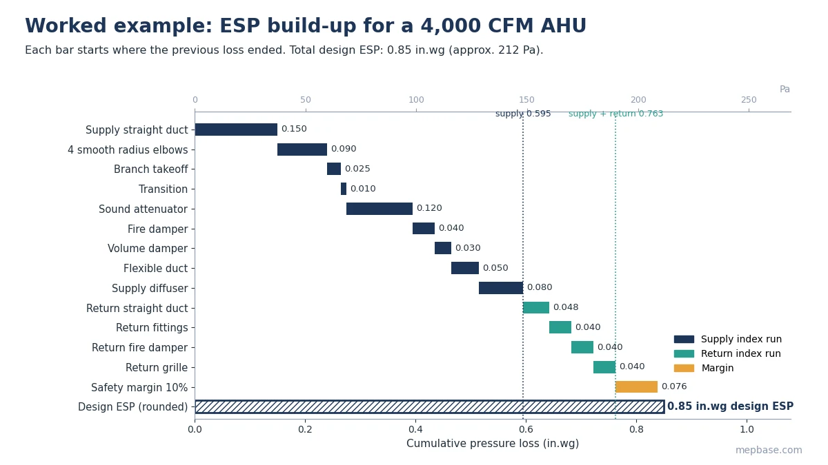
With ESP fixed, the manufacturer adds internal losses to get TSP. You can then estimate fan shaft power with the AHU Fan Shaft Power Calculator, or run your own numbers in the Fan Static Pressure Calculator.
ESP for ducted fan coil units
Ducted FCUs are usually available in standard ESP ratings of roughly 0.1 to 0.3 in.wg (25 to 75 Pa). Keep FCU duct runs short and simple, calculate the index run the same way, and pick the next standard ESP rating above your result. A high-ESP FCU selected “to be safe” is a common cause of noisy ceilings in hotel rooms and apartments.
Common mistakes
- Including the coil and filter losses in ESP. Those are internal to the unit and already counted by the manufacturer.
- Adding up all branches instead of following only the index run.
- Ignoring fittings. On short, fitting-heavy runs, fittings can be more than half the total loss.
- Using catalogue losses at the wrong airflow. Diffuser loss roughly quadruples when airflow doubles.
- Stacking safety factors at every step.
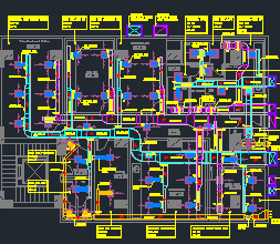
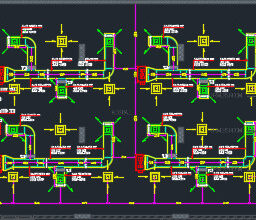
For real-world plant room layouts showing AHU connections, attenuators and dampers, download the AHU Plant Room Plan and Sections Shop Drawing.
Frequently asked questions
What is a typical ESP for an AHU?
For low-pressure comfort systems, 0.5 to 1.5 in.wg (125 to 375 Pa) is common. Systems with VAV boxes, long runs or attenuators sit at the higher end.
What is the difference between ESP and TSP?
ESP covers losses outside the unit. TSP is ESP plus the unit’s internal losses such as filters, coils and mixing sections.
Should I include the filter in ESP?
Not if the filter is inside the AHU. Include it only when it is a separate filter section or grille installed in the ductwork.
How do I convert in.wg to Pa?
1 in.wg = 249 Pa. So 0.85 in.wg is about 212 Pa.