Chilled Water Pump Head Calculation: Step-by-Step Guide with Worked Example
A chilled water pump that is sized wrong shows up quickly: starved coils at the far end of the building, or a pump running off its curve and wasting power. This guide walks through the chilled water pump head calculation step by step for closed-loop systems, with typical pressure drops and a full 300 TR worked example.
Why pump head matters
Pump head is the pressure the chilled water pump must add to circulate design flow through the worst circuit in the system. Undersize it and the farthest coils starve. Oversize it and the pump runs off its curve, wastes power, and control valves struggle to modulate.
This tutorial covers closed-loop chilled water systems. Open systems such as condenser water with cooling towers are covered briefly at the end.
Step 1: Confirm design flow
Flow comes from the cooling load and the design temperature difference:
Flow (GPM) = Tons × 24 / ΔT (°F)
Flow (L/s) = Load (kW) / (4.19 × ΔT (°C))
A 10°F (5.6°C) ΔT is traditional; many modern plants use 12 to 16°F (6.7 to 9°C) to cut flow and pump power. Use the Chilled Water Flow Calculator to check this quickly.
Step 2: Identify the index circuit
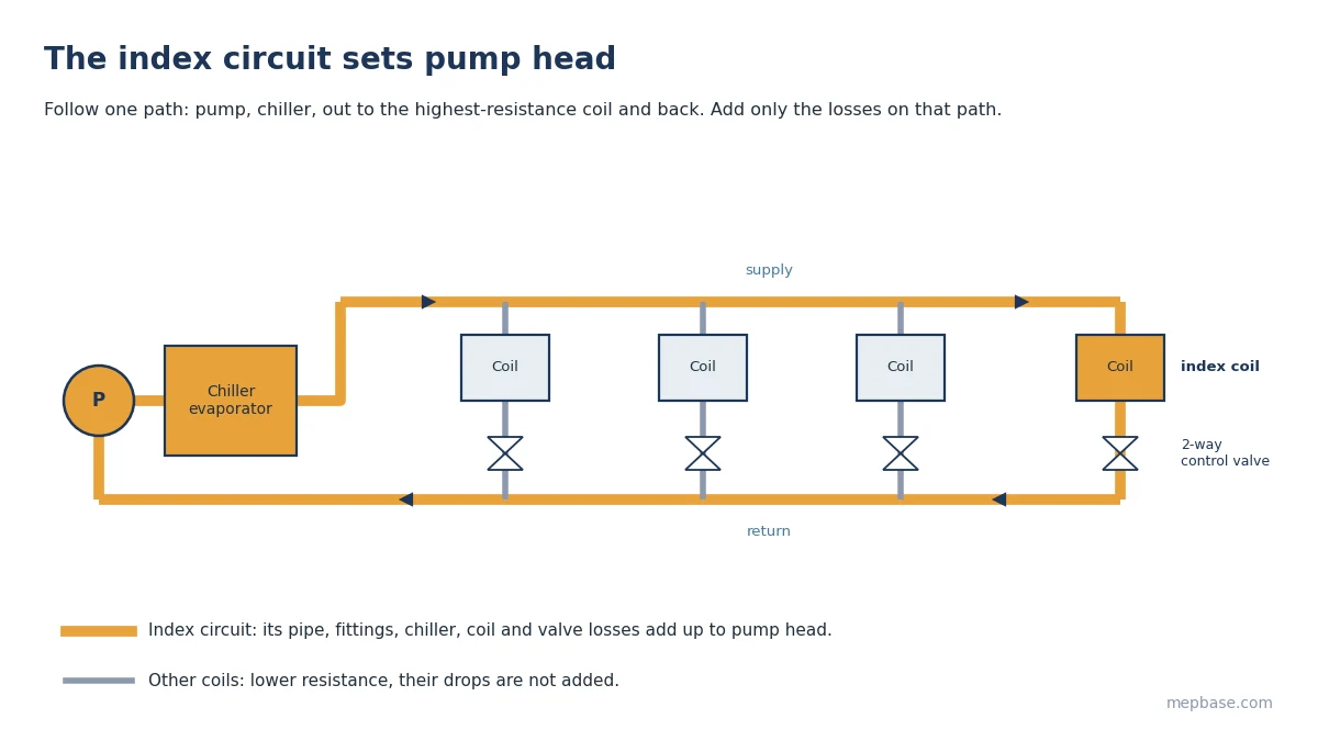
The index circuit is the path from the pump, through the chiller, out to the coil with the highest total resistance, and back. It is usually the farthest coil, but a nearer coil with a high-drop control valve or a large AHU coil can be worse. Check the two or three most likely candidates.
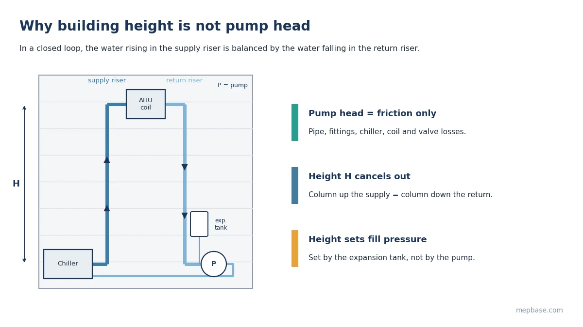
In a closed loop, static height does not count toward pump head. The water going up is balanced by the water coming down, so a 20-storey building does not need 20 storeys of head. Static height is handled by the expansion tank and the system fill pressure.
Step 3: Pipe friction loss
Add supply and return pipe lengths along the index circuit and multiply by the friction rate used for sizing:
Pipe loss = Total length × Friction rate / 100
Chilled water pipes are commonly sized for 1 to 4 ft per 100 ft (100 to 400 Pa/m). If you need to size the pipes first, see Chilled Water Pipe Sizing or use the CHW Pipe Calculator.
Step 4: Fittings
For detailed design, add equivalent lengths for each elbow, tee and reducer. For preliminary design, a fittings allowance of 30 to 50% of the straight pipe loss is a common rule. Use the higher end for plant rooms and risers packed with fittings.
Step 5: Equipment and valve pressure drops
Take these from manufacturer data at design flow. Typical ranges for preliminary work:
| Component | Typical drop (ft) | Typical drop (kPa) |
|---|---|---|
| Chiller evaporator | 10 to 25 | 30 to 75 |
| AHU cooling coil | 8 to 15 | 24 to 45 |
| FCU coil | 5 to 10 | 15 to 30 |
| 2-way control valve | 7 to 12 | 20 to 35 |
| Y-strainer (clean) | 3 to 6 | 9 to 18 |
| Check valve | 2 to 5 | 6 to 15 |
| Balancing valve | 3 to 5 | 9 to 15 |
Only count components that sit on the index circuit. Valves on other branches don’t add to pump head.
Step 6: Add a margin
Pump head = Pipe loss + Fittings + Equipment drops + Valve drops + Margin
A 10% margin is enough. Variable speed drives are now standard, so large margins only push the pump further from its best efficiency point.
Chilled water pump head calculation: worked example for a 300 TR chiller
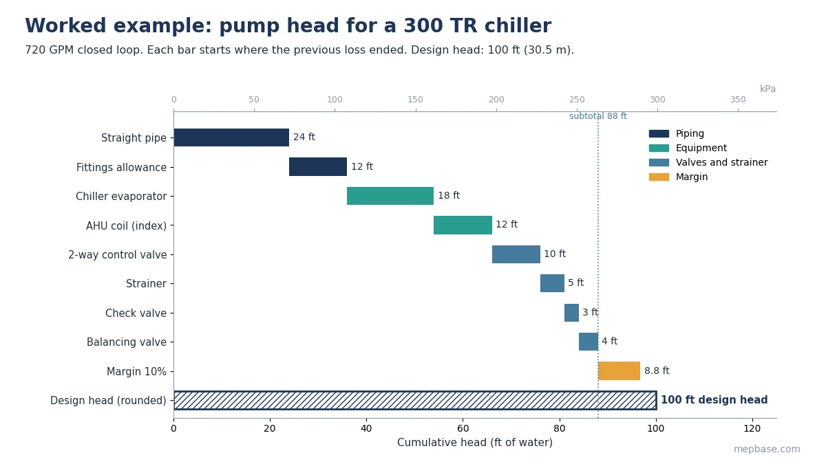
A 300 TR (1,055 kW) chiller serves AHUs with a 10°F ΔT. Supply and return pipe along the index circuit total 800 ft (244 m), sized at 3 ft per 100 ft.
Flow = 300 × 24 / 10 = 720 GPM (45.4 L/s)
| Item | Calculation | Head (ft) |
|---|---|---|
| Straight pipe | 800 × 3 / 100 | 24 |
| Fittings allowance | 50% of 24 | 12 |
| Chiller evaporator | manufacturer data | 18 |
| AHU coil (index) | manufacturer data | 12 |
| 2-way control valve | selected valve | 10 |
| Strainer | typical | 5 |
| Check valve | typical | 3 |
| Balancing valve | typical | 4 |
| Subtotal | 88 | |
| Margin 10% | 88 × 0.10 | 8.8 |
| Design pump head | 96.8, specify 100 ft (30.5 m) |
Pump shaft power:
BHP = GPM × Head (ft) / (3960 × Pump efficiency)
BHP = 720 × 100 / (3960 × 0.75) = 24.2 HP (18.1 kW), so select a 30 HP motor.
Check your own numbers with the Pump Head Calculator and the Pump Horsepower Calculator.
Primary-secondary and variable primary systems
In a primary-secondary system, the primary pump only covers the chiller loop (evaporator, chiller-side piping, decoupler) and the secondary pump covers the distribution loop out to the coils. Calculate each separately. In a variable primary system, one set of pumps covers both, so the chiller evaporator and the index coil circuit are in the same calculation, as in the example above.
Open loops: condenser water
Condenser water systems with open cooling towers are not closed loops. Add the static lift from the tower basin water level to the tower inlet and the nozzle or distribution pressure required by the tower manufacturer. Also check NPSH available at the pump suction with the Water Pump NPSH Calculator.
Common mistakes
- Adding building height to closed-loop pump head.
- Adding pressure drops from every coil instead of only the index circuit.
- Using a dirty-strainer drop as the design value and then adding a margin on top.
- Forgetting the chiller evaporator drop in variable primary systems.
For reference drawings, see the AutoCAD HVAC Chilled Water System DWG.
Frequently asked questions
Does building height affect chilled water pump head?
Not in a closed loop. Height affects the static fill pressure and the expansion tank, not the pump head.
What is a typical chilled water pump head?
For commercial buildings, 60 to 120 ft (18 to 37 m) is common. Long campus loops can be higher.
How do I convert ft of head to kPa?
1 ft of water is about 2.99 kPa, so 100 ft is about 299 kPa.
What pump efficiency should I assume?
Use 70 to 80% for preliminary sizing, then replace it with the selected pump’s actual efficiency at the duty point.