Fan Laws Explained: Affinity Laws, System Curves and VFD Energy Savings
Slow a fan down by 20% and it uses about half the power. That one fact is behind most HVAC fan energy savings, and it comes straight from the fan laws. This guide explains the fan laws (fan affinity laws) step by step: what they say, how fan and system curves interact, where the laws stop being accurate, and two worked examples, one for site balancing and one for VFD energy savings.
What are the fan laws?
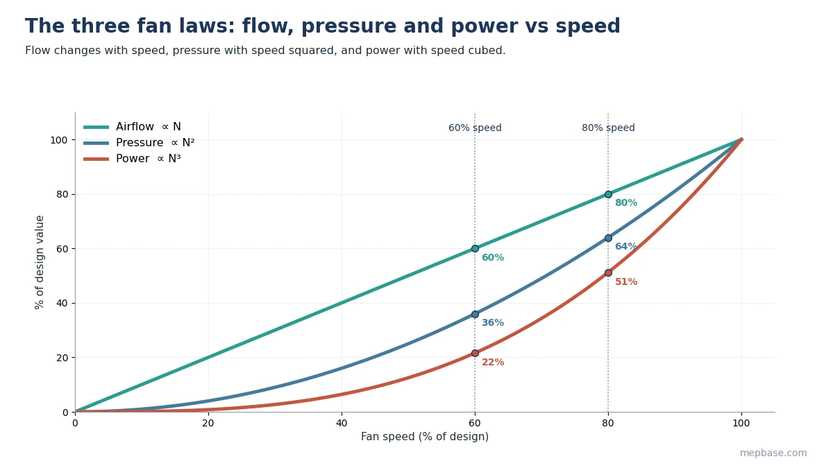
The fan laws describe how a fan’s airflow, pressure and power change when its speed, size or the air density changes, assuming the fan works on the same system curve. For a given fan running at a new speed:
Airflow: Q₂ / Q₁ = N₂ / N₁
Pressure: P₂ / P₁ = (N₂ / N₁)²
Power: W₂ / W₁ = (N₂ / N₁)³
Where N is fan speed (rpm), Q is airflow, P is pressure (static or total, used consistently) and W is shaft power.
The same relationships apply to centrifugal pumps, where they are called pump affinity laws.
Fan laws for size and air density
Two more sets of laws cover geometrically similar fans of a different size, and changes in air density (altitude or temperature), at the same speed:
| Change | Airflow | Pressure | Power |
|---|---|---|---|
| Speed N | ∝ N | ∝ N² | ∝ N³ |
| Wheel diameter D (similar fans) | ∝ D³ | ∝ D² | ∝ D⁵ |
| Air density ρ (same airflow) | unchanged | ∝ ρ | ∝ ρ |
The density law matters for fans handling hot air, such as smoke exhaust or kitchen exhaust, and for sites at high altitude: the fan moves the same volume but develops less pressure and draws less power than its catalogue rating at standard air.
Fan power formula
Fan shaft power at any operating point:
BHP = CFM × TSP (in.wg) / (6,356 × Fan efficiency)
kW = Airflow (m³/s) × TSP (Pa) / (1,000 × Fan efficiency)
Electrical input power is shaft power divided by motor and drive efficiency. Total static pressure (TSP) is the external static pressure plus the unit’s internal losses; see External Static Pressure (ESP) Calculation for AHU and FCU. You can check shaft power with the AHU Fan Shaft Power Calculator.
Fan curves and system curves
A fan does not choose its own operating point. It runs where its fan curve crosses the system curve. For a simple duct system with no fixed pressure requirement, the system curve is a parabola through zero:
ΔP = k × Q²
When the fan slows down, its curve drops, and the new operating point slides down that same parabola. Along this curve, the fan laws are accurate.
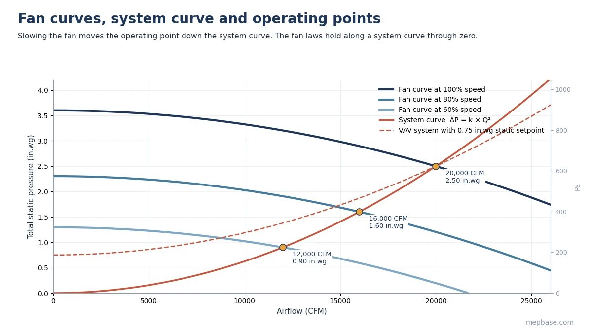
VAV systems are different. The fan is controlled to hold a minimum duct static pressure so the last VAV box still works (see VAV Box Sizing and Selection). Their system curve does not pass through zero, so at part load the fan runs at a higher pressure than the fan laws predict and saves less power. Static pressure reset, which lowers the setpoint when boxes are mostly open, recovers much of that loss.
Fan laws example 1: correcting airflow on site
During balancing, an AHU fan running at 1,100 rpm delivers 9,000 CFM at 2.0 in.wg TSP and draws 4.0 BHP. The design airflow is 10,000 CFM. The motor is rated 5 HP.
| Step | Calculation | Result |
|---|---|---|
| New speed | 1,100 × 10,000 / 9,000 | 1,222 rpm |
| Speed ratio | 1,222 / 1,100 | 1.111 |
| New pressure | 2.0 × 1.111² | 2.47 in.wg (615 Pa) |
| New shaft power | 4.0 × 1.111³ | 5.49 BHP (4.1 kW) |
| Motor check | 5.49 BHP > 5 HP motor | Motor overloaded: upgrade to 7.5 HP |
An 11% increase in airflow needs 37% more power. This is why speeding up a fan to fix low airflow often overloads the motor, and why the duct system should be checked for blockages or closed dampers first.
Fan laws example 2: VFD energy savings
A 20,000 CFM AHU runs at 2.5 in.wg TSP with a fan efficiency of 65%. Motor and VFD efficiency together are 90%. Over 6,000 hours a year it runs 1,000 h at full flow, 3,000 h at 80% and 2,000 h at 60%.
Design shaft power = 20,000 × 2.5 / (6,356 × 0.65) = 12.1 BHP, so electrical input = 12.1 × 0.746 / 0.90 = 10.03 kW.
| Flow (speed) | Power ratio | Input power | Hours | Energy |
|---|---|---|---|---|
| 100% | 1.000 | 10.03 kW | 1,000 | 10,030 kWh |
| 80% | 0.8³ = 0.512 | 5.14 kW | 3,000 | 15,420 kWh |
| 60% | 0.6³ = 0.216 | 2.16 kW | 2,000 | 4,320 kWh |
| VFD total | 6,000 | 29,770 kWh | ||
| Constant speed | 1.000 | 10.03 kW | 6,000 | 60,180 kWh |
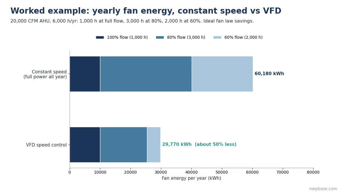
The ideal saving is about 30,400 kWh a year, roughly half the fan energy. Real savings are usually lower, because VAV systems hold a minimum static pressure and motor and drive efficiency fall at low load, but the order of magnitude is why VFDs are standard on HVAC fans. Convert units quickly with the Airflow Unit Converter and check pressures with the Fan Static Pressure Calculator.
When the fan laws are not accurate
- The system curve does not pass through zero, as in VAV systems with a static pressure setpoint or systems with a fixed back pressure.
- The fan is moved to a different part of its curve by damper changes rather than speed changes.
- Large speed reductions, where motor, drive and fan efficiencies drop.
- Changes in air density that are not accounted for, such as hot exhaust or high-altitude sites.
Pumps follow the same affinity laws; for pump head on closed loops, see Chilled Water Pump Head Calculation.
Common mistakes
- Applying the cube law to a VAV fan with a fixed static setpoint and overestimating savings.
- Increasing fan speed to fix low airflow without checking the motor’s power rating.
- Mixing static and total pressure between the before and after conditions.
- Forgetting that a hot-air fan develops less pressure than its standard-air catalogue rating.
- Using catalogue efficiency at design point for every part-load condition.
Frequently asked questions
What are the three fan laws?
Airflow changes with speed, pressure changes with speed squared, and power changes with speed cubed, for the same fan on the same system.
How much power does a fan save at 80% speed?
About 49% in theory, since 0.8³ = 0.512. Real savings are usually somewhat lower.
Do the fan laws apply to VAV systems?
Only approximately. VAV fans hold a minimum duct static pressure, so their system curve does not pass through zero and savings are less than the cube law predicts.
Are fan laws the same as affinity laws?
Yes. Fan laws are the affinity laws applied to fans; the same relationships apply to centrifugal pumps.