HVAC Shop Drawing DWG Free Download – Complete AutoCAD Ground Floor Layout
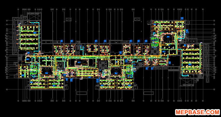
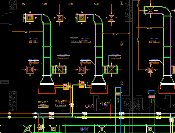
Looking for a professionally prepared HVAC shop drawing DWG free download that you can actually learn from and reuse on real projects? You are in the right place. In this post, MEP Base is sharing a complete, coordination-ready ground floor HVAC shop drawing in AutoCAD DWG format, prepared to real construction-site standards. This is not a basic schematic — it is a full working shop drawing with ductwork sizing, CFM tags, air outlet schedules, chilled water piping, AHU and FCU connections, bottom-of-duct (BOD) levels, legend, notes and key plan.
Whether you are an HVAC design engineer, a draftsman preparing shop drawings for consultant approval, or a fresh mechanical engineer trying to understand how professional MEP drawings are produced, this file will save you hours of drafting time and give you a real-world reference to follow.
Checking…
What Is an HVAC Shop Drawing?
An HVAC shop drawing is a detailed, dimensioned drawing prepared by the contractor (or their drafting team) based on the consultant’s design drawings. While design drawings show the general intent of the system, shop drawings show exactly how the system will be installed on site — with precise duct sizes, routing, elevations, equipment connections, damper locations, and coordination with the architectural ceiling, structure and other MEP services.
In simple words: the design drawing tells you what to install, and the shop drawing tells you how and where to install it. Consultants review and approve shop drawings before any fabrication or installation begins, which is why the quality of a shop drawing directly affects project approvals and site progress.
What Is Included in This HVAC Shop Drawing DWG File?
This DWG was produced in AutoCAD 2023 (DWG 2018 format) and represents the ground floor HVAC layout of a commercial building project. Here is a detailed breakdown of everything you will find inside the file after the free download:
1. Air Handling Unit (AHU) Connections
The drawing shows multiple AHU systems serving the ground floor, including fresh air (F/A) and treated air (T/A) connections for units such as AHU-02, AHU-03, AHU-05, AHU-14, AHU-16 and AHU-27, along with duct risers marked “UP TO ROOF” where the mains connect to rooftop equipment. Each AHU branch is tagged with its unit reference so you can trace every duct back to its source — exactly how a consultant expects a shop drawing to read.
2. Complete Ductwork Layout with Sizes and CFM Tags
Every supply, return, fresh air and exhaust duct in the drawing carries its size and airflow tag. Typical duct sizes used in the layout include:
- 36″ x 24″ and 26″ main supply ducts
- 22″ x 20″, 22″ x 10″ and 22″ x 8″ branch ducts
- 20″ x 16″, 20″ x 12″ and 20″ x 8″ secondary branches
- 18″ x 14″, 18″ x 12″ and 16″ x 10″ run-outs
- 8″ x 14″ and 6″ fresh air connections
Airflow tags range from small 450–500 CFM branches up to major duct mains carrying 2,940 CFM, 4,410 CFM and even 12,100 CFM — giving you a realistic picture of how duct sizing steps down along the run as air is distributed. This makes the file an excellent duct sizing reference for engineers who want to cross-check their own calculations against a real approved-style layout.
3. Air Outlets and Devices Schedule
The drawing includes a full range of professionally tagged air distribution devices:
- SAD – Supply Air Diffusers (16″x10″, 18″x12″, 18″x14″, 20″x8″, 22″x10″, 26″ and more)
- RAD – Return Air Diffusers (18″x12″, 28″ etc.)
- S.C.D – Supply Ceiling Diffusers (12″x12″, 150, 225, 300, 450 and 600 sizes)
- R.C.D – Return Ceiling Diffusers (150, 225, 300, 375 and 600 sizes)
- SG – Supply Grilles (SG-400)
- EX.AG – Exhaust Air Grilles
- Volume Dampers at branch take-offs for air balancing
4. Chilled Water Piping (CHWP) with GPM Tags
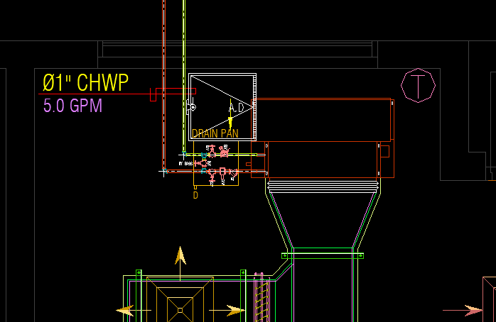
Alongside the air side, this shop drawing also covers the hydronic side. Chilled water supply and return piping is routed and sized from Ø1″ up to Ø4″, with flow tags such as 10 GPM, 16 GPM, 18 GPM, 26 GPM and 128 GPM on the mains. This is very useful if you want to study how chilled water piping is coordinated with ductwork in a real ceiling void.
5. Fan Coil Units, VRF and Refrigerant Piping
The layout includes FCU blocks with thermostat locations (FCU-THERMO), VRF units (2 TR capacity blocks) and refrigerant piping routes — so the file covers all three common HVAC system types found on commercial projects: ducted AHU systems, chilled water FCU systems, and DX/VRF systems.
6. Levels, Legend, Notes and Key Plan
What separates a shop drawing from a simple layout is coordination information, and this file has it:
- Bottom of Duct (BOD) levels — 3300 mm, 3800 mm and 4300 mm
- Ceiling levels (C.L) — 4600 mm and 4800 mm
- A proper legend and general notes block
- A key plan showing the drawing zone within the overall building
- Architectural background attached as Xref-style layers (walls, grids, room tags, ceiling), exactly as done in professional MEP drafting workflows.
Why Should You Download This HVAC Shop Drawing?
From my experience reviewing and preparing hundreds of MEP shop drawings, the fastest way to improve your drafting and design skills is to study real approved-quality drawings — not textbook diagrams. Here is what this free DWG download gives you:
- Ready-made HVAC CAD blocks: diffusers, grilles, dampers, FCUs, VRF units, AHU connections, pipe fittings and annotation tags you can copy into your own projects.
- Layer structure reference: see how ducts, chilled water piping, refrigerant piping, text and architectural backgrounds are separated into layers for clean plotting.
- Annotation standards: learn how duct size tags, CFM tags, GPM tags and BOD levels are placed so the drawing stays readable at plot scale.
- Coordination practice: study how duct routing avoids beams and fits within the ceiling void using BOD and ceiling level tags.
- Interview and training material: fresh engineers can use this drawing to understand real project terminology (SAD, RCD, F/A, T/A, CHWP, BOD) that appears in every MEP interview.
File Details
| File Name | HVAC_Shopdrawing.dwg |
| File Format | AutoCAD DWG (2018 format – opens in AutoCAD 2018 and later) |
| File Size | Approx. 7.5 MB |
| Category | HVAC / Mechanical Shop Drawings |
| Drawing Type | Ground Floor HVAC Layout (Ductwork + Chilled Water + VRF) |
| Units | Millimeters (duct sizes in inches, levels in mm) |
| Price | 100% Free Download |
How to Use This DWG File
- Click the download button below and wait for the timer to complete.
- Open the file in AutoCAD 2018 or any newer version (it also opens in free viewers like DWG TrueView, and in BricsCAD/ZWCAD).
- If the drawing opens with missing backgrounds, don’t worry — the architectural layers are embedded; simply thaw/turn on all layers from the Layer Manager.
- Use LAYISO and LAYUNISO commands to isolate the duct layers, piping layers or annotation layers while studying the drawing.
- Copy any blocks (diffusers, FCUs, tags, legend) into your own template using Ctrl+Shift+C (copy with base point) for reuse.
Free Download – HVAC Shop Drawing DWG
Click the button below to start your free download. No sign-up required — MEP Base shares professional MEP resources completely free for engineers, draftsmen and students.
Checking…
Related Free Downloads on MEP Base
If this file is useful for you, check out these related resources on our site:
- HVAC Drawings & CAD Blocks – Free DWG Downloads
- Plumbing Shop Drawings – Free DWG Files
- Electrical Layout Drawings – Free Downloads
- MEP BOQ Templates & Quantity Take-Off Sheets
Frequently Asked Questions (FAQs)
Is this HVAC shop drawing DWG really free to download?
Yes. This file is shared 100% free on MEP Base for educational and professional reference purposes. Just click the download button, wait a few seconds, and the file will be yours.
Which AutoCAD version do I need to open this file?
The file is saved in DWG 2018 format, so it opens in AutoCAD 2018 and all later versions (2019, 2020, 2021, 2022, 2023, 2024, 2025). It also works in DWG TrueView (free), BricsCAD and ZWCAD.
Can I use this drawing in my own projects?
You can use the blocks, tags, legend style and layer structure as a reference or starting template for your own shop drawings. Always update the layout, sizes and calculations to match your actual project design before submission.
What is the difference between a design drawing and a shop drawing?
A design drawing shows the consultant’s intent (system type, approximate routing, sizing basis), while a shop drawing is the contractor’s detailed installation drawing with exact routing, elevations, coordinated levels and equipment connections. Shop drawings must be approved before installation begins.
Does this file include duct sizing calculations?
The drawing includes duct sizes with their corresponding CFM tags, which you can use to reverse-check sizing (for example with the equal friction method), but it is a drawing file — separate calculation sheets are not included.
Final Words
A high-quality HVAC shop drawing is one of the best learning resources any mechanical/MEP engineer can have. This free HVAC shop drawing DWG download gives you a complete, real-project ground floor layout covering ductwork, air devices, chilled water piping, VRF systems and full coordination annotations — everything you need to study, practice and speed up your own drafting work.
If you found this file helpful, share this post with your colleagues and bookmark MEP Base — we upload new free MEP drawings, BOQ templates and CAD resources every week.