Fire Alarm Symbols DWG Free Download: Detectors, Modules & Panels
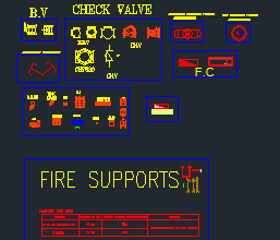
Fire alarm systems are essential life-safety components in modern buildings, and MEP engineers need accurate CAD symbols to produce clear, coordinated shop drawings. This free fire alarm symbols DWG provides a complete NFPA-style legend of addressable fire alarm devices, panels, wiring and clean agent suppression release devices, ready to use in AutoCAD and other CAD platforms.
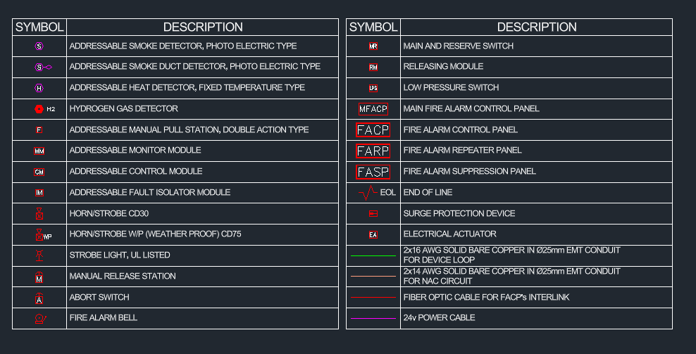
What’s Included in This Fire Alarm Symbols DWG?
Detection and Initiating Devices
- Addressable smoke detector (photoelectric type)
- Addressable smoke duct detector (photoelectric type)
- Addressable heat detector (fixed temperature type)
- Hydrogen (H2) gas detector
- Addressable manual pull station (double action type)
Modules and Notification Appliances
- Addressable monitor module, control module and fault isolator module
- Horn/strobe (30 cd) and weatherproof horn/strobe (75 cd)
- Strobe light (UL listed)
- Fire alarm bell
- End of line (EOL) device
- Surge protection device
Panels
- Main fire alarm control panel (MFACP)
- Fire alarm control panel (FACP)
- Fire alarm repeater panel (FARP)
- Fire alarm suppression panel (FASP)
Clean Agent Suppression Release Devices
- Releasing module
- Manual release station
- Abort switch
- Main and reserve switch
- Low pressure switch
- Electrical actuator
Wiring Legend
- 2 x 16 AWG solid bare copper in 25 mm EMT conduit for the device loop
- 2 x 14 AWG solid bare copper in 25 mm EMT conduit for the NAC circuit
- Fiber optic cable for FACP network interlink
- 24 V power cable
Fire Alarm Symbol Abbreviations
These are the tags used in this legend. Tags vary between consultants, so always match the project legend.
| Tag | Device |
|---|---|
| S | Addressable smoke detector |
| H | Addressable heat detector |
| F | Manual pull station |
| MM | Monitor module |
| CM | Control module |
| IM | Fault isolator module |
| RM | Releasing module |
| MR | Main and reserve switch |
| LPS | Low pressure switch |
| EA | Electrical actuator |
| EOL | End of line device |
| FACP | Fire alarm control panel |
| FARP | Fire alarm repeater panel |
| FASP | Fire alarm suppression panel |
Device Placement Quick Reference (NFPA 72)
Use these common limits as a starting point when placing symbols. Always follow the code edition and project specification that apply to your project.
- Smoke detectors (smooth ceiling): nominal spacing of 9.1 m (30 ft), with every point on the ceiling within 6.4 m (0.7 × spacing) of a detector.
- Heat detectors: spacing as per the detector’s listing, with every point within 0.7 × the listed spacing.
- Manual pull stations: within 1.5 m of each exit door, a maximum travel distance of 61 m to reach one, and the operating handle 1.07–1.22 m above the floor.
- Wall-mounted strobes: between 2.03 m and 2.44 m above the floor. A single 30 cd strobe covers a room up to about 8.5 m x 8.5 m, and a 75 cd strobe up to about 13.7 m x 13.7 m.
Drafting Tips for Better Fire Alarm Drawings
- Use separate layers for detectors, modules, notification appliances, wiring and panels.
- Show loop numbers and device addresses so the drawing matches the panel programming.
- Draw the device loop (SLC) and NAC circuits in different colours or linetypes, as in this legend, so they are easy to trace.
- Place a fault isolator module between zones or floors so one short circuit cannot take down the whole loop.
- Keep smoke detectors away from supply air diffusers, where airflow can stop smoke reaching them.
- Use hydrogen gas detectors in battery rooms and other areas where hydrogen can build up.
Clean Agent Suppression Interface
The suppression symbols in this DWG cover the fire alarm side of a clean agent system (such as FK-5-1-12 or FM-200 designed to NFPA 2001). The suppression panel or releasing module fires the electrical actuator on the agent cylinder, the manual release station lets occupants discharge the system by hand, and the abort switch holds the discharge while the area is checked. The low pressure switch monitors cylinder pressure, and the main and reserve switch selects which cylinder bank will discharge.
Fire Alarm Symbols DWG Free Download
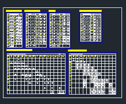
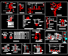
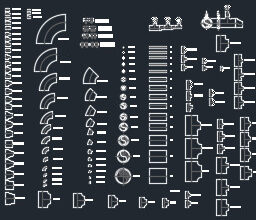
This DWG includes the complete fire alarm and suppression legend shown above.
Checking…
Frequently Asked Questions
What do CD30 and CD75 mean on a horn/strobe symbol?
They are the strobe’s light output in candela: 30 cd and 75 cd. Higher candela strobes cover larger rooms, and weatherproof outdoor units are usually specified at a higher rating.
What is the difference between a monitor module and a control module?
A monitor module brings an input into the addressable loop, such as a flow switch or tamper switch. A control module sends an output from the panel, such as releasing door holders, shutting down AHUs or switching a NAC circuit.
Why is the device loop wired in 16 AWG and the NAC in 14 AWG?
The device loop carries low-current data signals, so 16 AWG is enough. NAC circuits power horns and strobes, which draw much more current, so a larger 14 AWG cable keeps the voltage drop within limits at the end of the circuit.
Can I use these symbols in software other than AutoCAD?
Yes. The file is a standard DWG, so it opens in BricsCAD, DraftSight, ZWCAD and other DWG-compatible programs.
Related Downloads
- Fire Alarm Shop Drawing Free Download
- AutoCAD MEP Blocks Library
- Fire Sprinkler Distribution AutoLISP
- Electrical Typical Details DWG
Conclusion
This fire alarm symbols DWG gives MEP engineers, draftsmen and fire protection designers a complete NFPA-style legend in one file, from addressable detectors and panels to clean agent release devices. Combine it with the placement reference above to produce clear, accurate layouts from the first submission.