Deluge Foam-Water Sprinkler System DWG Free Download: Layout, Foam Equipment and Details
Water alone is not enough for flammable liquid and chemical storage fires. A deluge foam-water sprinkler system discharges a foam-water solution through open sprinklers over the whole protected area at once, smothering the fire and cooling the surroundings. This free AutoCAD DWG gives you a complete working set for one: sprinkler layout, cross-zoned fire detection and release, foam equipment schematic, isometric node diagram, and pipe hanger and support details.
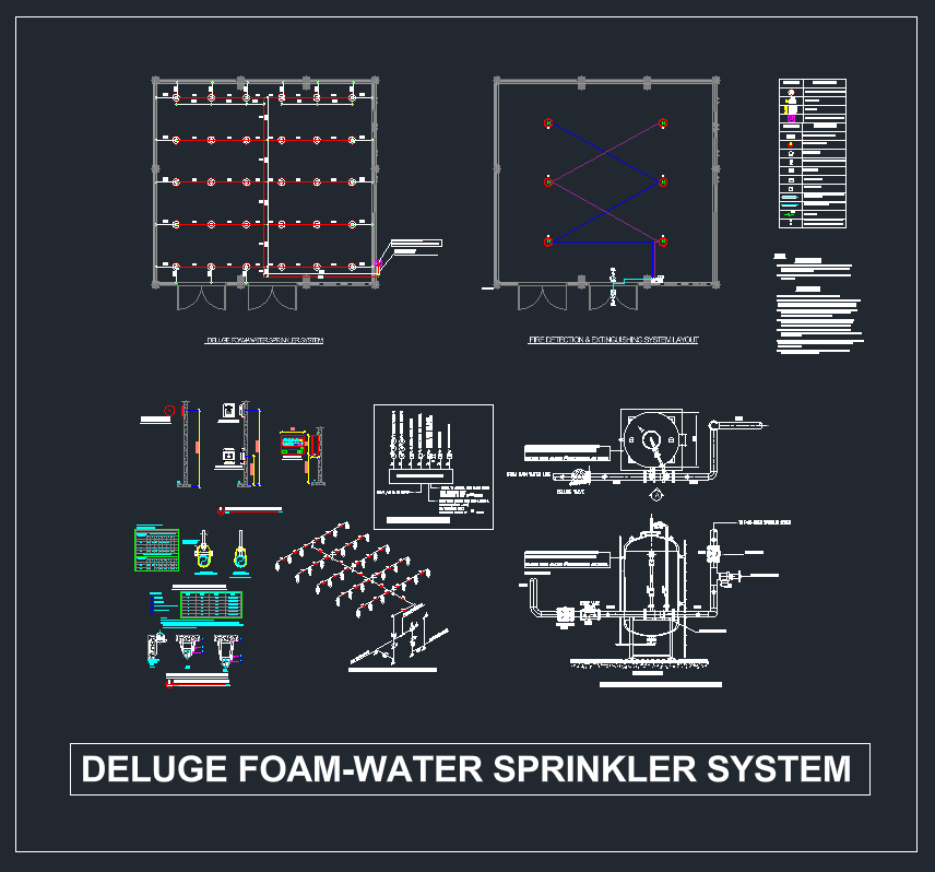
What’s Inside the DWG File?
- Deluge foam-water sprinkler system layout: pendent foam-water sprinklers on branch lines with pipe sizes from 25 mm to 100 mm.
- Fire detection and extinguishing system layout: 190°F heat detectors on two cross-zoned detection circuits (Z1 and Z2), with end-of-line devices.
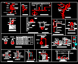
- Fire alarm equipment mounting details: horn with strobe, alarm bell, manual release station, abort switch and releasing panel with mounting heights.
- Extinguishing control panel schematic wiring diagram.
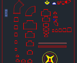
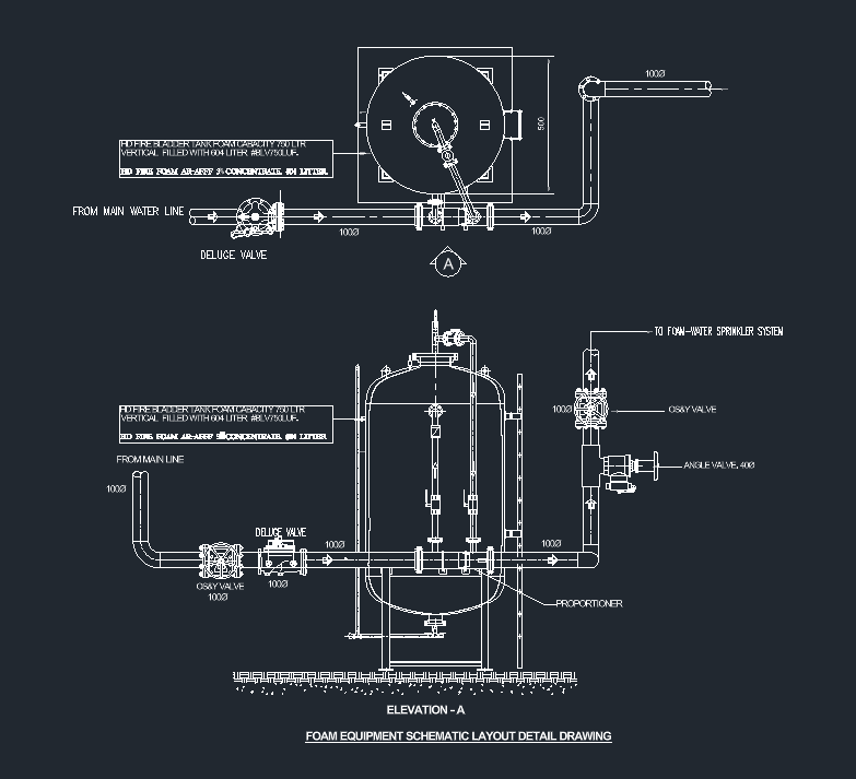
- Foam equipment schematic layout: vertical bladder tank, foam proportioner, deluge valve and OS&Y valves, in plan and elevation.
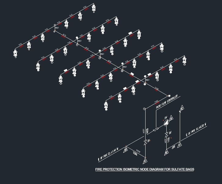
- Isometric node diagram: 42 numbered sprinkler points and hydraulic reference nodes N1 to N12, ready for hydraulic calculation.
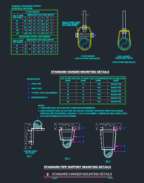
- Standard hanger and pipe support details: clevis and adjustable swivel loop hangers with dimension schedules, and wall and slab supports PS-1 to PS-3.
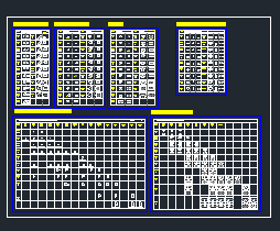
- Mechanical and electrical legends and general notes.
How a Deluge Foam-Water System Works
Unlike a wet pipe sprinkler system, a deluge system uses open sprinklers with no heat-sensitive element. The pipework downstream of the deluge valve is dry until the system operates, and then every sprinkler discharges at the same time. The sequence shown in this drawing is:
- Heat detectors on two separate detection circuits (Z1 and Z2) sense the fire. With cross-zoning, an alarm on one circuit alone only raises an alarm; both circuits must operate before release, which greatly reduces false discharges.
- The extinguishing (releasing) control panel sounds the alarm bell and horn-strobes, then sends a release signal to the solenoid on the deluge valve. A manual release station allows release by hand, and an abort switch can hold off release during the pre-discharge delay.
- The deluge valve opens and water flows from the main line through the foam proportioner.
- The proportioner draws foam concentrate from the bladder tank and mixes it into the water at 3%.
- The foam-water solution flows to all the open sprinklers in the protected area and is discharged at the same time.
Foam Equipment in This Drawing
| Component | As shown in the drawing |
|---|---|
| Foam concentrate tank | Vertical bladder tank, 750 L nominal capacity, filled with 604 L of concentrate |
| Foam concentrate | 3% AR-AFFF (alcohol-resistant aqueous film-forming foam) |
| Proportioner | Ratio flow controller between the deluge valve and the system riser |
| Deluge valve | Electrically released, with solenoid actuator wired to the releasing panel |
| Isolation valves | OS&Y valves on the main line and system riser, with a 40 mm angle valve |
| Main line | 100 mm (4 in) from the water supply to the proportioner |
AR-AFFF is suitable for both hydrocarbon fuels and polar solvents (such as alcohols), which is why it is common for chemical and mixed storage areas.
Quick Check: How Long Will the Foam Last?
Foam concentrate is used at the proportioning rate, so the tank size sets the maximum solution flow for the required discharge time:
Concentrate needed (L) = Solution flow (L/min) × Proportioning rate × Discharge time (min)
NFPA 16 generally requires enough concentrate for at least 10 minutes of foam discharge at the design flow. For the 604 L of 3% concentrate in this drawing:
Maximum solution flow = 604 / (0.03 × 10) = 2,013 L/min (about 532 GPM)
If the hydraulic calculation for the sprinkler system shows a higher flow, the tank must be larger. You can run the system flow with the Deluge System Calculator and check sprinkler flow with the Sprinkler K-Factor Calculator.
Isometric Node Diagram for Hydraulic Calculation
The isometric shows every sprinkler numbered (1 to 42) and the main hydraulic nodes (N1 to N12) from the remote branch back to the deluge valve and proportioner, with pipe sizes and lengths. Because every sprinkler in a deluge system flows at once, the hydraulic calculation covers the whole system rather than a single remote design area. For foam-water deluge systems over flammable liquids, a design density of at least 0.16 GPM/ft² (6.5 L/min/m²) is common. Check density with the Sprinkler Density Calculator and the full hydraulics with the Fire Hydraulic Calculator.
For the general method, see Fire Fighting System Design Calculation.
Fire Alarm and Release Equipment Mounting Heights
The drawing notes give these mounting requirements:
| Device | Mounting height (to bottom of device) |
|---|---|
| Manual release station | 1.20 m to 1.40 m above finished floor |
| Extinguishing control panel | Not less than 1.40 m above finished floor |
| Audible and visual alarm devices | Not less than 2.40 m above finished floor, and at least 0.30 m below the ceiling |
Other notes in the drawing: EMT conduit for all fire alarm wiring, 1.5 mm² thermoplastic-covered stranded cable for detectors, manual stations, sounders, strobes and the release solenoid, fire-retardant sealant at all pipe and cable openings, and design to NFPA 16 and the local civil defence code. Detector and device locations are indicative and must be verified on site.
Pipe Hanger and Support Details
The hanger sheet covers clevis hangers for 2-1/2 in (65 mm) pipe and above and adjustable swivel loop hangers for 2 in (50 mm) and below, each with a full dimension schedule. The support details PS-1 to PS-3 show wall-mounted and slab-mounted angle bar supports with galvanized U-bolts for pipes up to 80 mm, with U-bolt, expansion bolt and angle sizes for each pipe size.
Who Can Use This DWG?
- Fire protection engineers designing foam-water systems for chemical, flammable liquid and storage areas
- Draftsmen preparing shop drawings and civil defence submittals
- Contractors planning installation of deluge valves, foam tanks and release systems
- Students learning how detection, release and foam discharge work together
Download Deluge Foam-Water Sprinkler System DWG
Click below to download the AutoCAD file. The link will appear after a short wait. Use it as a reference and adapt sizes, quantities and details to your project’s hazard, hydraulic calculation and authority requirements.
Checking…
Related Fire Fighting Resources
- Fire Fighting Alarm Valve Set Detail DWG
- Fire Fighting CAD Details Free Download
- Fire Alarm AutoCAD Blocks DWG
- Fire Fighting Valves, Pumps and Dynamic Fittings DWG Blocks
- Fire Pump Room DWG
Frequently Asked Questions
What is a deluge foam-water sprinkler system?
It is a fixed system with open sprinklers that discharges a foam-water solution over the whole protected area at once when the deluge valve opens. It is designed to NFPA 16 and used for flammable liquid and chemical hazards.
What is the difference between a deluge system and a wet pipe sprinkler system?
A wet pipe system has closed sprinklers that open individually from heat. A deluge system has open sprinklers and dry pipework, and all sprinklers discharge together when a detection system opens the deluge valve.
Why are the detectors cross-zoned?
Cross-zoning needs two separate detection circuits to alarm before the system releases. This prevents a single faulty detector from discharging foam over the whole area.
How much foam concentrate does a foam-water system need?
Solution flow × proportioning rate × discharge time. With 3% concentrate and 10 minutes of discharge, every 1,000 L/min of solution flow needs 300 L of concentrate.