Fire Fighting CAD Details Free Download (DWG) — 19 Standard Details Explained
Looking for ready-made fire fighting CAD details for your shop drawings? This free DWG package contains 19 standard fire protection installation details taken from real approved project drawings — covering wet sprinkler systems, deluge systems, FM200 clean agent suppression, fire hydrants, pump room accessories and every pipe support you’ll need to close out a fire fighting submittal.
Below, each detail is explained the way a consultant reviews it: what it shows, the key dimensions and components, and where it’s used. The complete DWG file is available for free download at the end of this post — no signup required.
What’s Inside the Fire Fighting Details DWG Package?
- Alarm check valve and deluge valve trim details
- Pendent sprinkler, water spray nozzle and test drain details
- FM200 gas suppression system schematic
- Fire hydrant, fire department connection (Siamese) and service box
- Jockey pump installation and air release valves
- Full set of pipe supports: clevis/swivel hangers with spacing table, trapeze, floor, wall and slab supports, plus pipe sleeves and underground burial detail
- Fire extinguisher mounting detail
1. Alarm Check Valve Detail (Wet Sprinkler System)
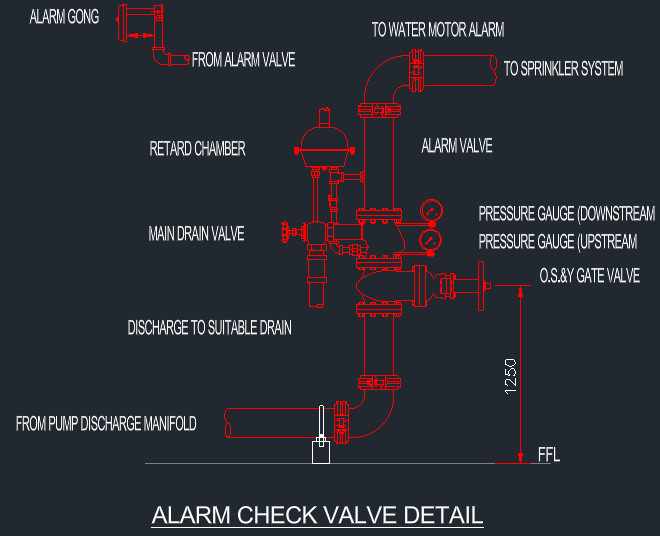
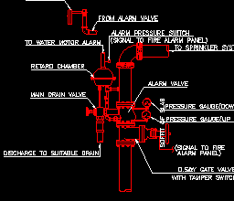
The heart of every wet pipe sprinkler zone. The detail shows the riser from the pump discharge manifold up to the sprinkler system, with the alarm valve, retard chamber (to prevent false alarms from pressure surges), connection to the water motor alarm gong, upstream and downstream pressure gauges, main drain valve discharging to a suitable drain, and an O.S.&Y. gate valve — with the trim set at 1250 mm above FFL for access.
2. Air Release Valve Detail
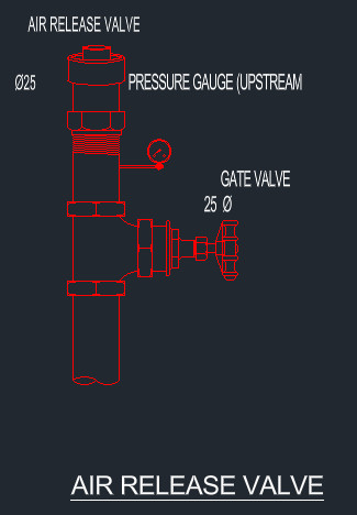
Installed at system high points to purge trapped air that causes water hammer and corrosion in fire mains. The detail shows a Ø25 air release valve tee’d off the riser with an upstream pressure gauge and a 25 mm gate valve for isolation during maintenance.
3. Water Spray Nozzle Detail
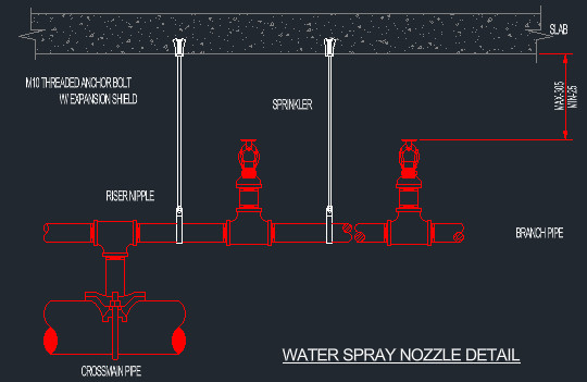
Used on water spray (open nozzle) systems protecting transformers, fuel areas and similar hazards. Nozzles mount on riser nipples off the branch pipe, fed from the crossmain, with the branch suspended from the slab on M10 threaded anchor bolts with expansion shields — maximum drop 305 mm, minimum 25 mm.
4. FM200 Gas Suppression System
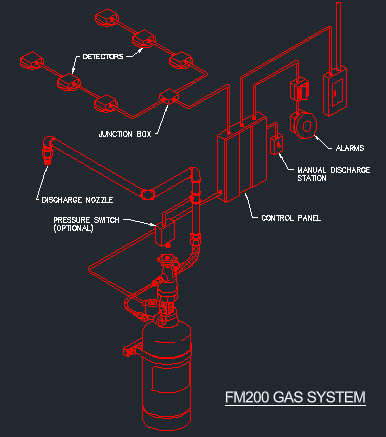
A complete clean agent system schematic for server rooms and electrical rooms: the FM200 cylinder with discharge piping and discharge nozzle, optional pressure switch, cross-zoned detectors wired through junction boxes to the control panel, plus alarms and the manual discharge station. Ideal for coordinating fire fighting and ELV scopes on one drawing.
5. Deluge Valve Detail
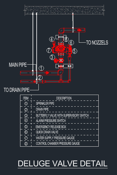
For open-head deluge zones. The trim is keyed to an 8-item table: sprinkler pipe, drain pipe, butterfly valve with supervisory switch, alarm pressure switch, emergency release box, quick drain valve, and separate water supply and control chamber pressure gauges — main pipe in, distribution to nozzles, and drain piped away.
6. Pipe Support Through Wall & Hanger Through Slab
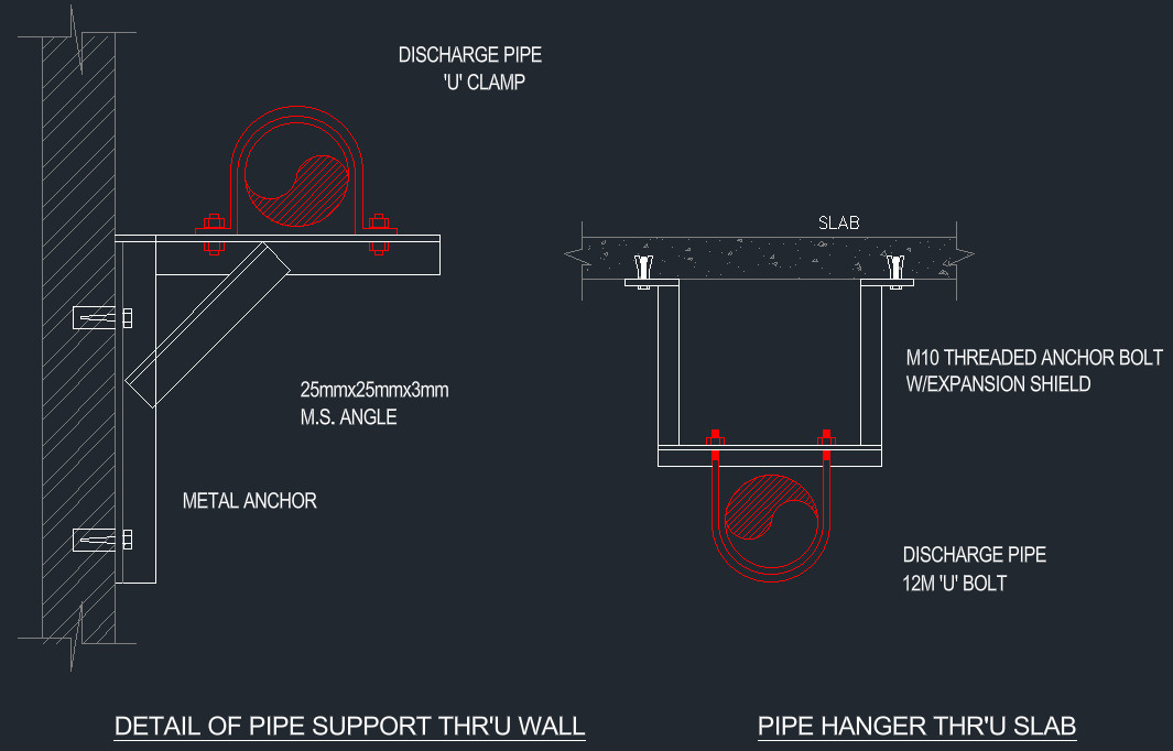
Two support conditions on one detail: a wall bracket made of 25×25×3 mm M.S. angle with metal anchors carrying the discharge pipe in a U-clamp, and a slab-hung trapeze on M10 threaded anchor bolts with expansion shields holding the pipe with a 12M U-bolt.
7. Test Drain Valve Detail
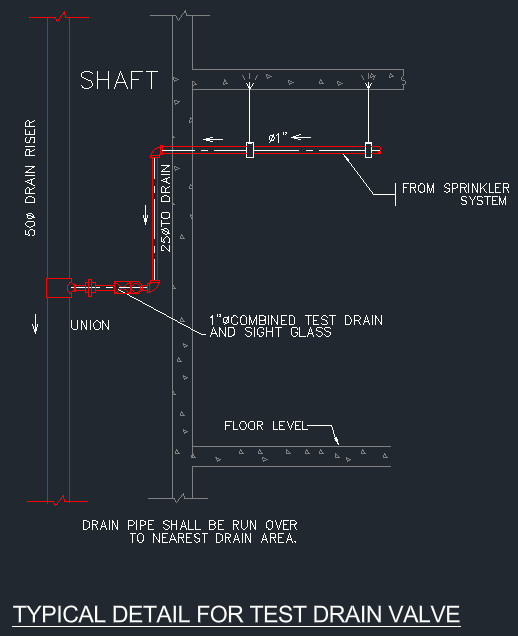
Every sprinkler zone needs an inspector’s test connection. This typical detail shows the 1″ combined test drain and sight glass off the sprinkler system, dropping via 25Ø drain into the 50Ø drain riser in the shaft, with a union for maintenance — and the note that drain pipe shall run to the nearest drain area.
8. Pipe Floor Support Detail
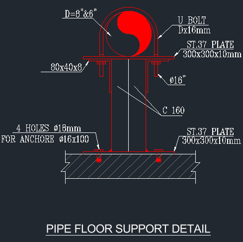
For pump rooms and roof mains: 8″ and 6″ pipes held by a 16 mm U-bolt on an ST.37 plate (300×300×10 mm), on a C160 channel post welded to a matching base plate, anchored with 4 nos. Ø16×100 anchors (Ø18 holes).
9. Sprinkler Pipe Hanger & Spacing Table (Clevis / Swivel)
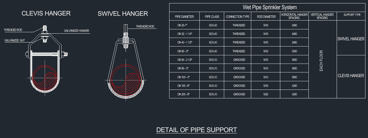
The most valuable sheet in the set: clevis and swivel hanger details plus a complete wet pipe sprinkler hanger schedule — DN25 to DN200, SCH-40 threaded up to 2″ and SCH-10 grooved above, rod diameters M10 to M22, and horizontal spacing from 2400 mm (small bore) to 4200 mm (6″–8″), with vertical support at each floor. Swivel hangers for small threaded pipe, clevis hangers for grooved sizes.
10. Pendent Sprinkler Detail
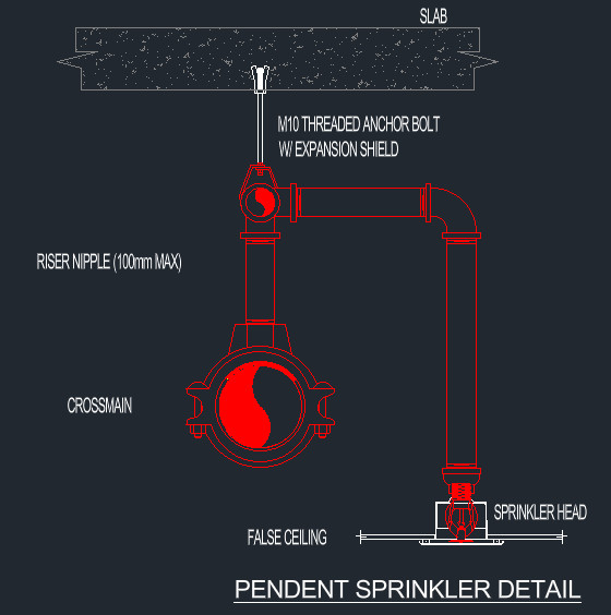
The standard drop from crossmain (grooved coupling shown) to the sprinkler head at the false ceiling — riser nipple limited to 100 mm max, hung from the slab with an M10 anchor bolt and expansion shield, with the escutcheon finishing flush at ceiling level.
11. Fire Hydrant Installation Detail
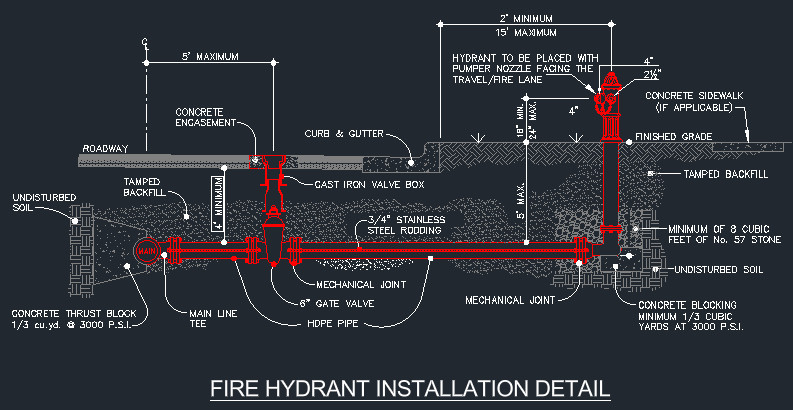
A full civil-coordinated hydrant detail: main line tee off the HDPE fire main with concrete thrust block (1/3 cu.yd. at 3000 PSI), 6″ gate valve in a cast iron valve box with concrete encasement, mechanical joints with 3/4″ stainless steel rodding, hydrant set 2’–15′ from the curb with the pumper nozzle facing the fire lane, minimum 8 cubic feet of No. 57 stone for barrel drainage, tamped backfill and concrete blocking.
12. Fire Hose Service Box (Outdoor Hydrant Box)
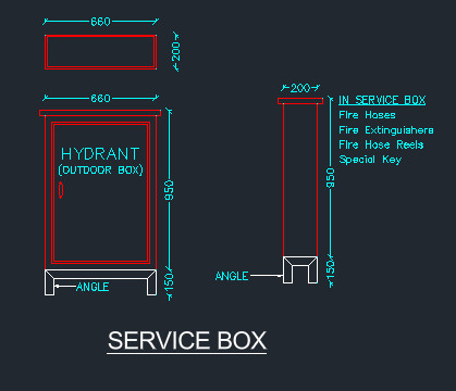
The outdoor cabinet that accompanies hydrant installations: 660 × 950 × 200 mm box on 150 mm angle legs, housing fire hoses, fire extinguishers, hose reels and the special key.
13. Pipe Sleeve Detail (Wall & Slab)
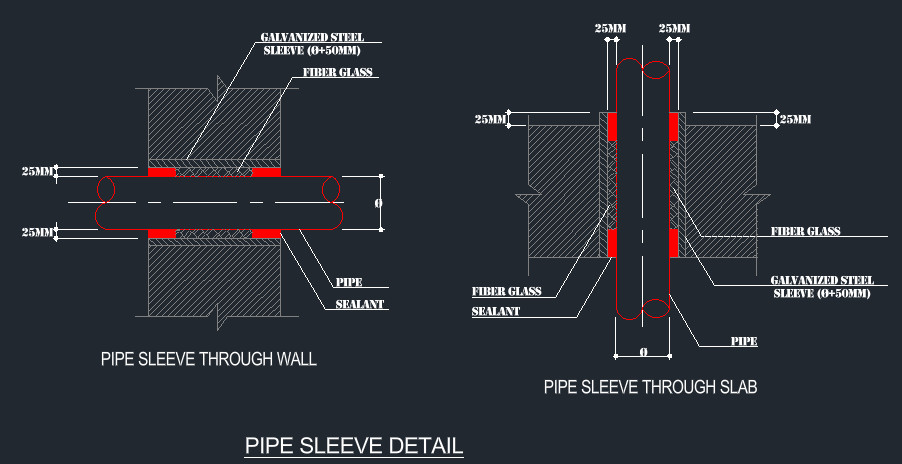
Fire-rated penetrations done right: a galvanized steel sleeve sized Ø+50 mm through the wall or slab, packed with fiberglass and finished with sealant 25 mm on both faces. Both wall and slab conditions are drawn.
14. Fire Extinguisher Mounting Detail
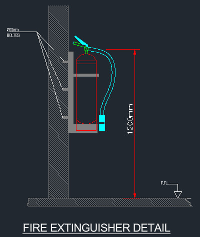
Simple but always requested by civil defense: extinguisher on a wall bracket fixed with Ø10 mm bolts, handle at 1200 mm above FFL.
15. Fire Department Connection (Siamese) Detail
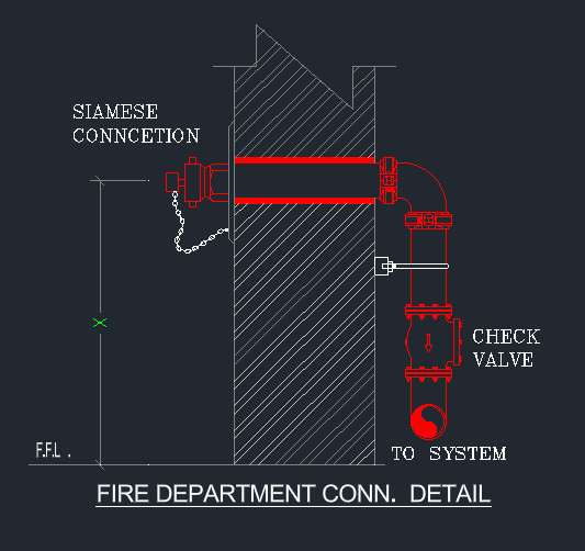
The FDC that lets the fire brigade boost the system: Siamese connection with caps and chains through the external wall, dropping through a check valve into the system riser.
16. Trapeze Support Detail (Group of Pipes)
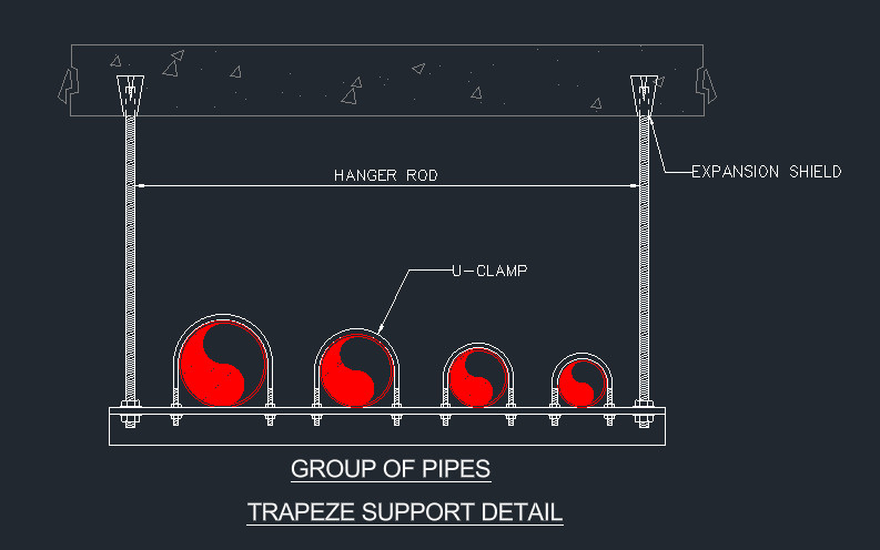
Where several fire mains run together, a trapeze on two hanger rods with expansion shields carries the whole group, each pipe secured with its own U-clamp to the common channel — cleaner than individual hangers and easier to coordinate above ceilings.
17. Jockey Pump Installation Detail
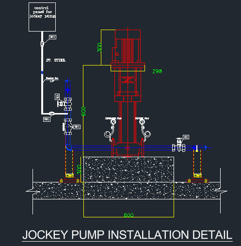
The pressure-maintenance pump of the fire pump set: vertical multistage jockey pump on an 800 mm concrete pad, with isolation valves, check valve and sensing line in stainless steel to the jockey pump control panel. Pair this with your fire pump room layout for a complete NFPA 20-style submittal.
18. Underground Fire Pipe Installation Detail
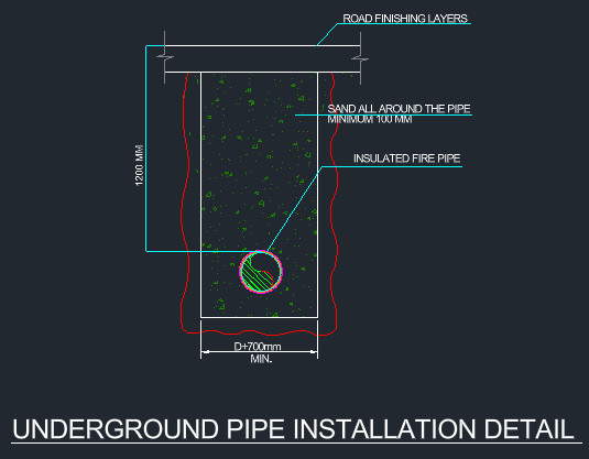
Trench detail for buried fire mains: insulated fire pipe at 1200 mm depth below road finishing layers, bedded in minimum 100 mm sand all around, with trench width D + 700 mm minimum.
19. Automatic Air Release Valve — Parts Detail
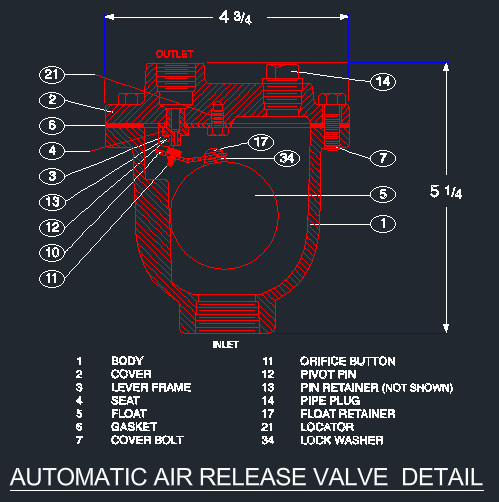
A manufacturer-style cutaway (4¾” × 5¼”) with a numbered parts list — body, cover, lever frame, seat, float, gasket, cover bolt, orifice button, pivot pin, retainers, pipe plug, locator and lock washer. Useful for O&M manuals and material submittals.
How to Use These Details in Your Shop Drawings
Insert the blocks into your project title block, renumber them per your drawing register, and edit dimensions/materials to match your project specification and approved submittals (pipe class, hanger spacing and burial depth vary by spec and local civil defense requirements). For the electrical side of the fire pump room, size the feeders and breakers with our Electrical Panel Load Calculator, back up the fire alarm panel with the UPS Sizing Calculator, and design the voice evacuation system with the PA Speaker & Amplifier Calculator.
Free Download — Fire Fighting Details DWG
All 19 details are included in a single AutoCAD file (DWG, compatible with AutoCAD 2004 and later). Free for personal and professional use — a link back to MEPBase is appreciated.
Checking…
Frequently Asked Questions
Are these fire fighting CAD details free to download?
Yes. The DWG file with all 19 details is completely free to download and use in your projects. No registration or payment is required.
Which AutoCAD version do I need to open the file?
The file is saved in AutoCAD 2004 (AC1018) format, so it opens in AutoCAD 2004 and every later version, as well as free viewers like DWG TrueView and most BIM/CAD packages that import DWG.
Are these details code-compliant with NFPA?
They follow common practice aligned with NFPA 13 (sprinklers), NFPA 14 (standpipes), NFPA 20 (fire pumps) and NFPA 2001 (clean agents), but they are typical details from approved project drawings — always verify dimensions, hanger spacing and materials against your project specification and local civil defense requirements before submission.
Can I edit and reuse the details in my shop drawings?
Yes. That is exactly what they are for — insert them into your title block, renumber them per your drawing register, and adapt materials and dimensions to your approved submittals.
What is the difference between an alarm check valve and a deluge valve?
An alarm check valve serves wet pipe systems with closed sprinkler heads — water flow through the valve triggers the alarm. A deluge valve serves open-nozzle systems and stays closed until released by the detection system or emergency release, then floods all nozzles in the zone at once.
Why is a jockey pump needed in a fire pump set?
The jockey pump maintains system pressure and compensates for small leaks, so the main fire pump does not start on minor pressure drops. It starts first at a higher cut-in pressure; the main pump starts only when demand exceeds jockey capacity, as arranged in NFPA 20 pressure settings.