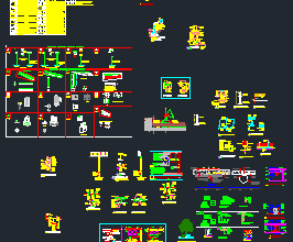
Earthing & Lightning Protection Details DWG – 37 Electrical Typical Details (Free Download)
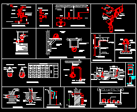
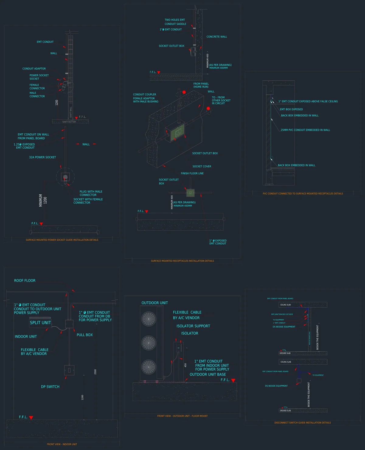
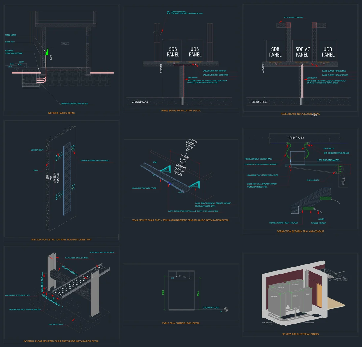
This free earthing and lightning protection details DWG is a complete electrical typical details sheet taken from a live Gulf commercial project. It has 37 coordinated AutoCAD details in one file. They cover earthing pits, rebar bonding, ESE lightning protection, roof copper tape, internal earth bars, lighting fixture mounting, power sockets, split AC power supply, panel boards and cable tray supports. Every detail sits in an equal-size frame with a title strip, so you can copy any single detail straight into your shop drawing or submittal sheet.
Most free electrical detail files online cover lighting and sockets only. This sheet also includes the earthing and lightning protection system (LPS) details that consultants ask for during material and shop drawing approval, and it puts them on the same drawing as the containment and panel details. All linework, text, hatches and dimensions sit on six clean named layers, so you can freeze the text or hatching in one click.
Checking…

File Specifications
| File format | DWG (AutoCAD 2018 format, opens in AutoCAD 2018 and later) |
| Number of details | 37 typical details on one sheet |
| Units | Millimetres |
| Layers | 6 clean layers: DETAILS, TEXT, HATCH, DIMS, FRAME and TITLE |
| Layout | 6 columns, uniform frames with title strips, ready for A0 plotting |
| Discipline | Electrical: earthing, LPS, lighting, power, containment |
| Price | Free |
What Is Inside the DWG
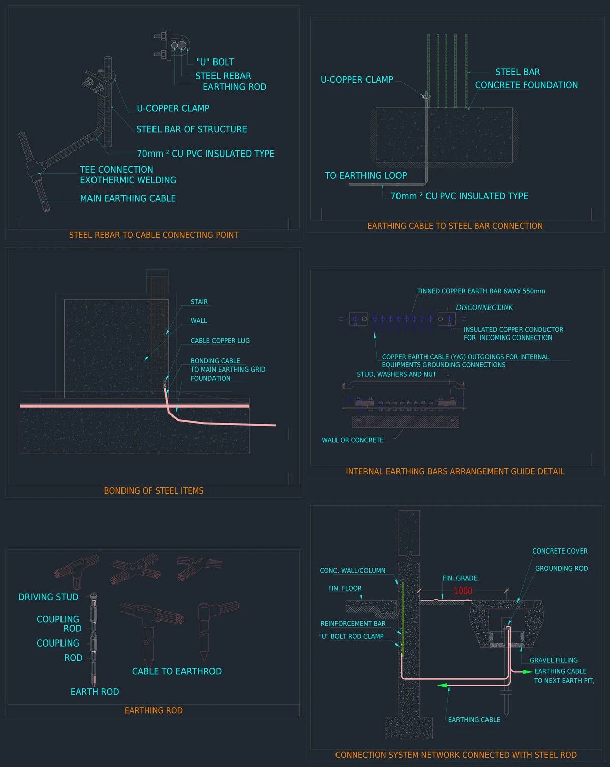
Earthing System Details (6 details)
- Earthing cable to steel rebar connection using a U-type copper clamp and 70 mm² Cu/PVC insulated cable taken to the earthing loop.
- Steel rebar to cable connecting point with an exothermic welded tee joint on the main earthing cable.
- Earth pit with grounding rod, gravel filling and concrete cover, plus the link from a column rebar using a U-bolt rod clamp.
- Earthing rod assembly showing the driving stud, rod couplings and cable-to-rod connectors.
- Bonding of steel items such as stair stringers to the main earthing grid with a copper lug.
- Internal earth bar arrangement: tinned copper bar on insulators with a disconnect link, an insulated incoming conductor and Y/G outgoing equipment earths.
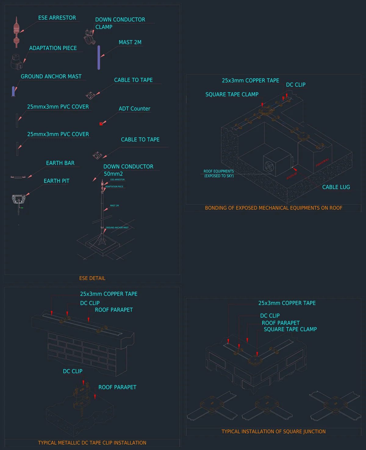
Lightning Protection (LPS) Details (4 details)
- ESE (Early Streamer Emission) air terminal detail with adaptation piece, 2 m mast, ground anchor mast, down conductor clamp, lightning strike counter, PVC cover and earth pit.
- Roof parapet 25 x 3 mm copper tape fixing with DC clips.
- Square tape clamp junctions for tee and cross connections of the roof mesh.
- Bonding of exposed roof mechanical equipment to the roof tape.
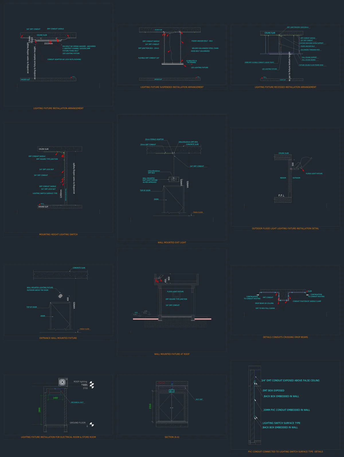
Lighting Installation Details (12 details)
- Surface, suspended (chain and hook bolt) and recessed false-ceiling fixture arrangements with EMT and liquid-tight flexible conduit.
- Lighting switch mounting height at 1200 mm above FFL.
- Wall-mounted exit light above a door, outdoor flood light, roof wall fixture and entrance wall fixture.
- Electrical room and store room lighting with section.
- Conduits crossing drop beams with pull elbow and saddle clamps.
- Transition from embedded PVC conduit in the wall to exposed EMT above the false ceiling.
Power, AC and Containment Details (15 details)
- Surface-mounted socket outlets at a minimum of 400 mm AFF, a 32A industrial socket at 1200 mm, and the receptacle conduit transition.
- Split AC indoor unit with DP switch at 1200 mm, plus the outdoor unit isolator on a support beside the unit.
- Disconnect switch installed beside the equipment.
- Incomer cable entry through a 1000 x 1000 x 1000 mm manhole and DN100 underground PVC pipes.
- Panel board installation with a vertical 200 x 100 mm HDG cable tray, gland plates and conduit risers.
- Wall-mounted cable tray, tray trunk with wall brackets and earth jumper, tray-to-conduit connection, floor-mounted external tray, tray change of level, and a 3D view of the electrical room panels.
Standards Referenced
These details follow common Gulf consultant practice. Always check the edition named in your project specification, because the governing standard varies from project to project.
- IEC 62305-3:2010: physical damage protection, air termination, down conductors and the earth termination system.
- NF C 17-102:2011: the French standard most Gulf specifications cite for ESE air terminals, protection radius and installation.
- IEC 62561 series (Part 1:2017 and Part 2:2018): test requirements for LPS clamps, connectors, conductors and earth electrodes.
- BS 7430:2011+A1:2015: code of practice for protective earthing.
- IEC 60364-5-54:2011: selection and erection of earthing arrangements and protective conductors.
- SBC 401 (Saudi Building Code, Electrical, 2018 edition) for projects in KSA, together with the local utility requirements for incoming supply and metering.
- IEC 61537:2006: cable tray and cable ladder systems.
Practical Notes From Site Experience
The values below are typical values used on Gulf projects. They are not code minimums. Confirm each one against your approved specification and consultant comments.
- Earth resistance: specifications commonly ask for 1 Ω or less for the main earthing system, and 10 Ω or less for each LPS earth termination. Note the required value on your earth pit detail. Without it, the detail usually comes back with a comment.
- Test joint and disconnect link: every down conductor needs a test joint above ground. The internal earth bar should have a removable link so that each earth pit can be tested on its own.
- Exothermic welding versus clamps: buried and concealed joints are normally exothermic welded. Bolted clamps are kept for accessible points only.
- Roof tape bonding: bond every exposed metallic roof item to the roof tape, including AC outdoor units, handrails, water tanks and cat ladders. Consultants check this on site before roofing works close out.
- Panel height: keep the highest operating handle of a panel within the reachable height in your specification, typically 2000 mm or less. Also keep a clear working space in front of each panel, and check your room layout against it before you issue the panel detail.
- Cable tray supports: use the support spacing recommended by the tray manufacturer for the cable load. The sheet shows 1500 mm on vertical runs, which is a safe typical value for wall-mounted trays.
- Outdoor isolators: specify a weatherproof enclosure (IP65 or higher is typical) for AC outdoor isolators. Use liquid-tight flexible conduit for the final connection.
Useful Tools for Earthing and Cable Design
Size the conductors shown in these details with the free calculators on MEPBase Tools:
- Earthing Calculator: earth conductor and electrode sizing.
- Cable Size Calculator and Voltage Drop Calculator: for incomer and final circuits.
- Short Circuit Calculator: fault level checks for earthing conductor sizing.
- Lighting Lux Calculator: fixture quantities for the lighting layouts.
Related Electrical Downloads
- AutoCAD Electrical Installation Details DWG
- Electrical Installation Detail DWG Library
- AutoCAD Electrical Symbols DWG
- Lighting System Shop Drawing DWG
- Street Light Installation Detail DWG
- Cable Size Calculation Guide
- AutoCAD SHX Fonts (if any text shows as question marks when you open the file)
Frequently Asked Questions
Which AutoCAD version do I need to open this DWG?
The file is saved in AutoCAD 2018 format. It opens in AutoCAD 2018 and all later versions, and also in DWG TrueView and most DWG-compatible CAD software.
What is an ESE lightning arrester?
An Early Streamer Emission (ESE) air terminal emits an upward streamer earlier than a conventional rod, which gives it a larger protection radius. It is installed on a mast and connected to the earth termination through a down conductor. NF C 17-102:2011 is the standard most Gulf specifications refer to for ESE systems.
What size copper tape is used for roof lightning protection?
This sheet uses 25 x 3 mm bare copper tape, which gives a 75 mm² cross-section. That is a common choice on Gulf projects. The minimum cross-sections are given in IEC 62305-3, so confirm the size against your specification.
What earth resistance value should an earth pit achieve?
No single value applies to every project. Typical specification values are 1 Ω or less for the main system earth and 10 Ω or less for each LPS earth termination. Always use the value stated in your approved project specification.
Why are earthing cables connected to the foundation rebar?
Bonding the structural rebar to the earthing system makes the foundation act as an additional earth electrode, which lowers the overall earth resistance. It also equalises potential across the building and is accepted under BS 7430 and IEC 62305-3.
Can I use these details in my project shop drawings?
Yes. The file is free for project use. Treat the details as typical references only, and update the dimensions, sizes and notes to match your approved design and specification before submission.