Alarm Valve CAD Block – Free DWG with Alarm Check Valve Detail and Fire Alarm Symbols
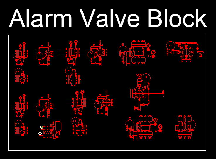
This free alarm valve CAD block file puts three fire protection drawing sets into one DWG: a fully labelled alarm check valve detail, a sheet of wet alarm valve blocks in several views, and a combined fire alarm and voice evacuation symbol legend. Each set can be copied directly into sprinkler shop drawings, riser schematics and legend sheets without redrawing.
The content suits drawings prepared to NFPA 13 (2025 edition) for sprinkler work and NFPA 72 (2025 edition) for fire alarm and emergency communication systems. The legend also carries items common on Gulf submittals, such as an auto-dialler interlocked to the Civil Defence authority and central battery emergency lighting.
What Is Included in This Alarm Valve CAD Block DWG
The file contains three separate drawings:
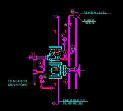
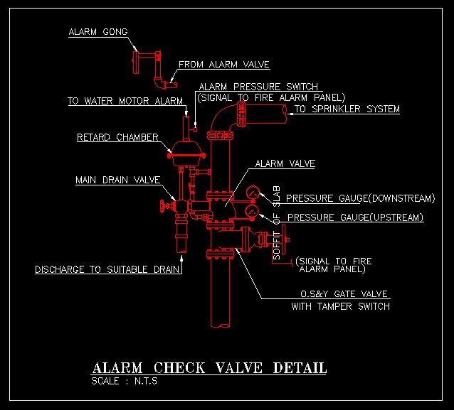
- Alarm check valve detail: a riser elevation with every trim component tagged.
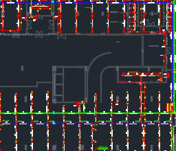
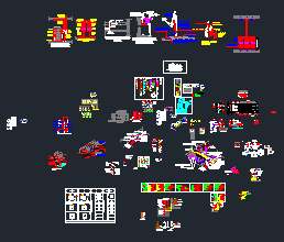
- Alarm valve block set: multiple trimmed alarm valve assemblies in elevation and plan.
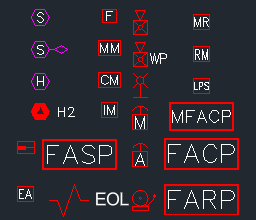
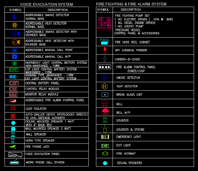
- Fire alarm and voice evacuation legend: two symbol tables totalling 38 symbols.
1. Alarm Check Valve Detail (N.T.S)
The first drawing is an elevation of a wet alarm check valve on a vertical riser, drawn not to scale. Every component carries its own leader and text, so the detail can go onto a sheet as it is. The labelled items are:
- OS&Y gate valve with tamper switch, annotated as a signal to the fire alarm panel
- Alarm valve body with flanged connections
- Pressure gauge on the upstream (supply) side
- Pressure gauge on the downstream (system) side
- Main drain valve with discharge to a suitable drain
- Retard chamber on the alarm line
- Take-off to the water motor alarm
- Alarm gong fed from the alarm valve
- Alarm pressure switch, annotated as a signal to the fire alarm panel
- Riser outlet bend to the sprinkler system
- Soffit of slab reference line
The detail marks both signal points, the tamper switch and the alarm pressure switch, as connections to the fire alarm panel. That makes it a practical reference on interface drawings where the sprinkler contractor and the fire alarm contractor need to agree on who provides which device and where the monitor modules go.
2. Alarm Valve Block Set
The second sheet collects alarm valve assemblies drawn as individual blocks. It includes front elevations, side elevations and plan views of trimmed valves, with retard chambers, gauges, drain valves and alarm line piping drawn on the trim. The right-hand side of the sheet carries larger flanged assemblies with full trim pipework, suitable where the valve station needs to be shown at a bigger drawing scale.
Having the same valve in elevation and plan lets you keep a valve room plan, a riser diagram and a section through the valve station consistent with one another. The blocks are drawn in red line work, so they stand out against architectural backgrounds.
3. Fire Alarm and Voice Evacuation Legend
The third drawing contains two legend tables side by side. Each has a symbol column and a description column.
| Legend Table | Symbols Included |
|---|---|
| Voice Evacuation System (22 symbols) | Addressable smoke and heat detectors on normal base and with sounder base, addressable manual call point (indoor and weatherproof), emergency light and exit light on central battery, hanging exit sign, central battery panel, control relay module, monitor relay module, addressable fire alarm control panel, loop isolator, auto-dialler to Civil Defence, ceiling speaker 1 W with back box, wall speaker 2 W, wall speaker, horn speaker, fire phone jack, voice evacuation panel, microphone call station |
| Fire Fighting & Fire Alarm System (16 symbols) | Fire pump set (electric, diesel and jockey pump with pressure vessel and control panel), fire hose reel cabinet, dry chemical powder extinguisher, CO2 extinguisher, fire alarm control panel (zones/loop), smoke detector, heat detector, break glass unit, bell, weatherproof bell, sounder, sounder and strobe, emergency light, exit light, fire hydrant, ceiling speaker |
The first table suits addressable systems with voice evacuation. The second suits conventional fire alarm layouts combined with fire fighting equipment. Keep only the table that matches your project and delete the other, so the legend sheet does not show two different symbols for the same device.
Drawing Details
| File format | DWG (AutoCAD) |
| Drawings in file | 3 (valve detail, block set, legend) |
| Detail scale | N.T.S |
| Legend symbols | 38 |
| Reference standards | NFPA 13 (2025), NFPA 72 (2025) |
| Price | Free |
Where to Use These Blocks
- Sprinkler shop drawings: valve room plans, riser diagrams and valve station sections.
- Fire alarm drawings: legend sheets, device layouts and riser schematics.
- Interface drawings: showing tamper and flow signal points between the sprinkler and fire alarm systems.
- Tender and authority drawings: consultant-style legends for Civil Defence submittals.
Tips for Working With the File
- Check the
INSUNITSsetting before inserting blocks into your drawing, so millimetre and inch drawings do not scale incorrectly. - The alarm check valve detail is N.T.S. Place it on a detail sheet rather than scaling it into a plan.
- Replace the blank duty point in the pump set description with your actual flow and pressure, using consistent units.
- Match the legend symbols to the ones already used on your device layouts before issuing the drawing set.
For pipe sizing, pump duty and other checks on the same project, use the free calculators at tools.mepbase.com.
Download Alarm Valve CAD Block DWG
Checking…
Frequently Asked Questions
Is an alarm valve the same as an alarm check valve?
Yes. Both names describe the same device used on wet pipe sprinkler systems. It is a check valve with a clapper that lifts when a sprinkler operates, which lets water into the alarm port to drive the water motor gong and operate the pressure switch.
What does the retard chamber in the detail do?
The retard chamber sits on the alarm line and absorbs short pressure surges from the supply. This stops the pressure switch and water motor alarm from giving false alarms when the clapper lifts briefly without a sprinkler flowing.
Why are both the tamper switch and pressure switch connected to the fire alarm panel?
They send different signals. The tamper switch on the OS&Y gate valve reports a supervisory signal when the valve is moved from its open position. The alarm pressure switch reports a waterflow alarm signal. NFPA 72 treats these as separate signal types, so both are monitored.
Do the legend symbols follow NFPA 170?
The legend uses symbols common on consultant drawings in the Gulf region. It is not a strict reproduction of NFPA 170 (2024 edition). If your project specification calls for NFPA 170 symbols, check each symbol against the standard before issue.
What should I do if the DWG does not open in my AutoCAD version?
Open the file in Autodesk DWG TrueView, which is free, and use its DWG Convert function to save a copy in an older DWG format your AutoCAD version can read.