How to Size HVAC Ducts Online (Step-by-Step with Examples)

Sizing a duct used to mean spinning a cardboard ductulator wheel and reading numbers off a tiny scale. Today you can do the same job in a browser in under a minute. This guide walks you through sizing round and rectangular ducts online, step by step, with four worked examples you can copy straight into your own calculations.
Want to skip straight to the tool? Open the free online ductulator in a new tab and follow along.
What You Need Before You Start
Collect these four inputs first and the tool does the rest.
- Airflow in CFM or L/s for the section of duct you are sizing. This comes from your cooling load; if you only know the tonnage, convert it with the TR to CFM calculator.
- Design friction rate or velocity. Most comfort systems use 0.08–0.10 in.wg per 100 ft (0.65–0.85 Pa/m) for supply ducts.
- Space limits such as ceiling void depth or shaft width, which usually fix one side of a rectangular duct.
- Total equivalent length (TEL) of the index run: straight duct plus the equivalent length of every elbow, tee and transition.
Step-by-Step: Sizing a Duct Online
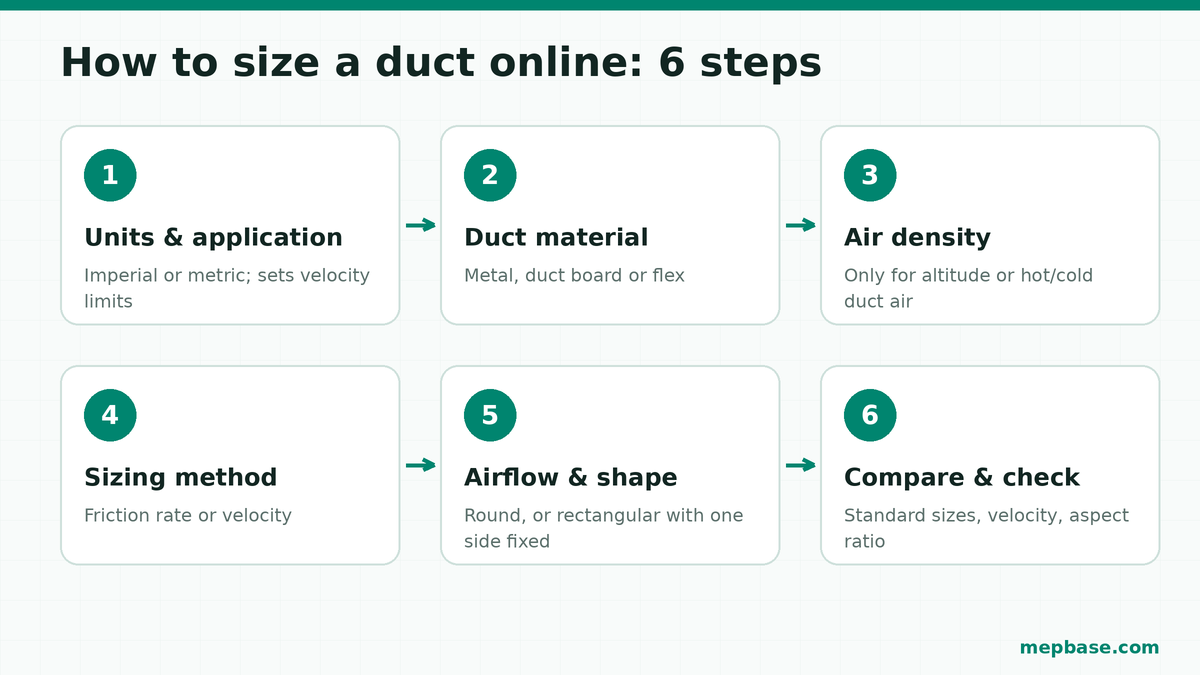
Step 1: Choose Units and Application
Select imperial (CFM, in.wg, fpm, inches) or metric (L/s, Pa/m, m/s, mm). The application setting only sets the velocity limits used for warnings; it does not change the sizing maths.
Step 2: Pick the Duct Material
Galvanised sheet metal is the smoothest option. Duct board needs roughly a 6% larger diameter for the same friction rate, and fully stretched flexible duct about 12% larger. The tool applies these corrections automatically.
Step 3: Correct for Air Density (Only If Needed)
Leave this at 0 ft and 70°F for standard conditions. Open it when the site is at altitude or the duct carries very hot or cold air. Always enter the temperature of the air inside the duct, not the outdoor temperature. For example, 800 CFM of cooled supply air at 55°F on a site at 2,000 ft is about 4% below standard density, so the calculated diameter drops slightly from 12.8 in to 12.7 in.
Step 4: Choose the Sizing Method
Use friction rate for a complete supply or return system, so pressure drop stays consistent across every branch. Use velocity where noise or a fixed route governs, such as a short main next to an occupied room. If you are unsure which suits your project, read equal friction vs velocity method for duct sizing.
Step 5: Enter the Airflow and Duct Shape
Type in the airflow and choose round or rectangular. For rectangular duct, enter the side your ceiling void allows and the tool solves the other side on standard 2 in (50 mm) increments.
Step 6: Compare the Standard Sizes and Read the Warnings
The exact diameter almost never matches a stocked size, so the tool shows the standard size either side with its real velocity and friction. Pick the one that suits the project, then check the warnings for velocity limits and aspect ratio before the size goes on a drawing.
Worked Examples
All four examples below were run in the duct sizer with galvanised metal duct at standard air.
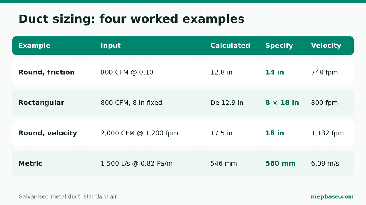
| Example | Input | Calculated | Specify | Velocity | Friction |
|---|---|---|---|---|---|
| 1. Round, friction method | 800 CFM at 0.10 in.wg/100 ft | 12.8 in | 14 in | 748 fpm | 0.064 in.wg/100 ft |
| 2. Rectangular, 8 in void | 800 CFM at 0.10 in.wg/100 ft, one side fixed at 8 in | De 12.9 in | 8 × 18 in | 800 fpm | 0.098 in.wg/100 ft |
| 3. Round, velocity method | 2,000 CFM at 1,200 fpm | 17.5 in | 18 in | 1,132 fpm | 0.102 in.wg/100 ft |
| 4. Metric, friction method | 1,500 L/s at 0.82 Pa/m | 546 mm | 560 mm | 6.09 m/s | 0.72 Pa/m |
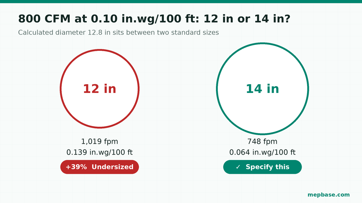
Example 1: Why 14 in and Not 12 in?
800 CFM needs 12.8 in, which sits between two standard sizes. A 12 in duct runs at 1,019 fpm with a friction rate of 0.139 in.wg/100 ft — 39% above the design target. A 14 in duct runs at 748 fpm and 0.064 in.wg/100 ft. The 12 in duct is undersized, so specify 14 in. Over a 120 ft TEL the 14 in duct gives a total pressure drop of only 0.076 in.wg.
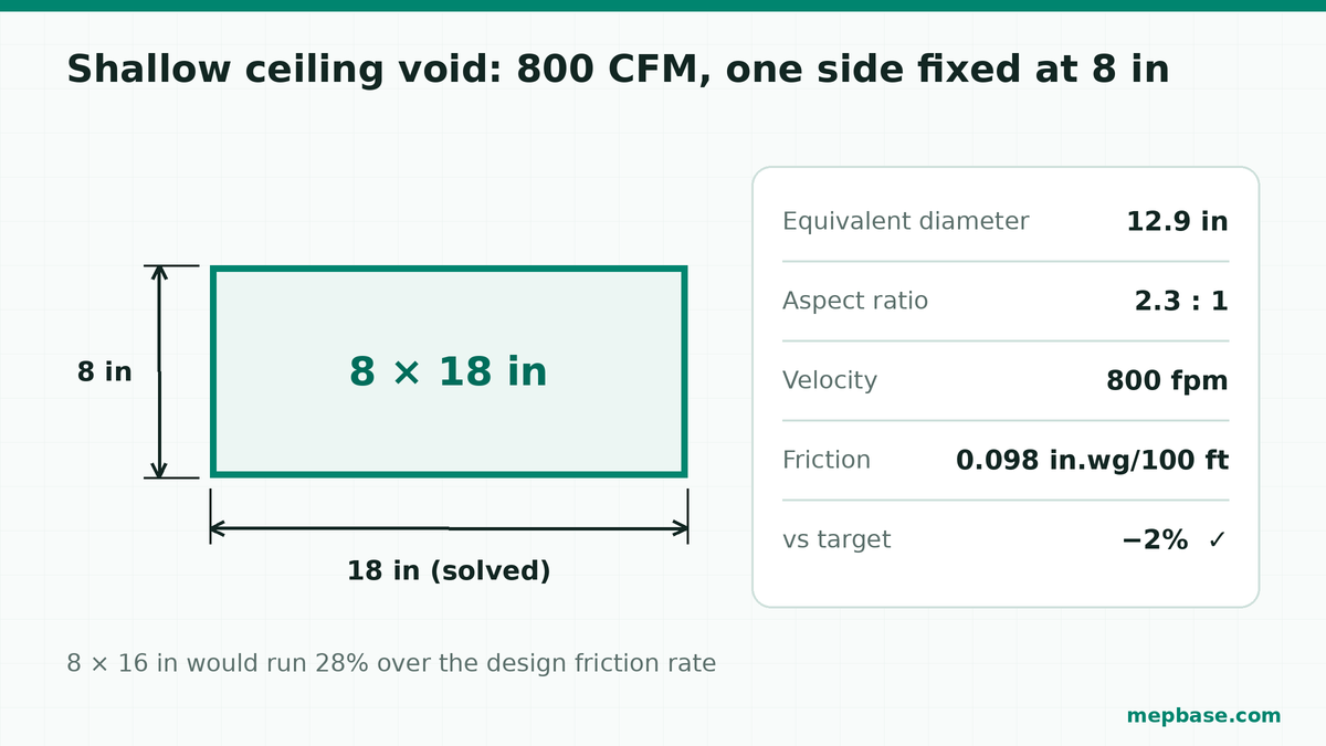
Example 2: A Shallow Ceiling Void
With only 8 in of depth available, the tool offers 8 × 16 in (0.128 in.wg/100 ft, 28% over target) or 8 × 18 in (0.098 in.wg/100 ft, 2% under). It recommends 8 × 18 in. The aspect ratio is 2.3:1, well inside the SMACNA limit of 4:1.
Example 3: Sizing by Velocity
At 1,200 fpm, 2,000 CFM needs 17.5 in. A 16 in duct would run at 1,432 fpm, 19% above the target, so the tool recommends 18 in at 1,132 fpm. Over 150 ft TEL the total pressure drop is 0.153 in.wg — the figure you take to the fan static pressure calculator.
Checking an Existing Duct
Switch the tool to Duct size → get airflow when you need to know what an existing or proposed duct can carry. A 12 × 16 in rectangular duct at 0.10 in.wg/100 ft carries about 1,243 CFM at 932 fpm, with an equivalent round diameter of 15.1 in. Useful when a refit adds a larger unit to old ductwork.
If you prefer to work with four values at once — entering any two of airflow, friction, velocity and diameter — use the duct calculator instead.
Common Mistakes to Avoid
- Always rounding up. One size up in round duct can drop the friction rate 40% or more below design, adding cost and space for no benefit. Compare both options first.
- Leaving fittings out of the TEL. Elbows and tees often add more pressure drop than the straight duct itself.
- Using outdoor temperature for density. The air inside a cooled supply duct is cold, not hot, so the correction is much smaller than most people expect.
- Pushing aspect ratio past 4:1. Split the run into two parallel ducts instead.
- Treating flex duct as metal. Compressed flex can multiply pressure drop several times over; keep runs short and tight.
Related Guides and Tools
- Duct size chart PDF — free download
- Equal friction vs velocity method for duct sizing
- HVAC load calculation guide
- AC tonnage chart
- Online ductulator — round and rectangular duct sizer
Frequently Asked Questions
How do I size a duct online?
Enter the airflow and a design friction rate (typically 0.1 in.wg per 100 ft) or velocity into an online ductulator, choose round or rectangular, and compare the standard sizes either side of the calculated diameter. Pick the size that keeps friction and velocity within your design limits.
What friction rate should I use for supply ducts?
Most comfort systems use 0.08–0.10 in.wg per 100 ft (0.65–0.85 Pa/m) for supply ducts and 0.05–0.08 in.wg per 100 ft for return ducts. Lower values give quieter, larger ducts; higher values give smaller ducts with more fan energy.
What size duct do I need for 800 CFM?
At 0.1 in.wg per 100 ft, 800 CFM needs a 12.8 in round duct, so specify 14 in. A 12 in duct would run 39% above the design friction rate. A rectangular option for an 8 in deep ceiling void is 8 × 18 in.
Should I always round up to the next duct size?
No. When the smaller standard size stays within about 2% of the design friction rate, it is usually the better choice. Rounding up blindly can leave ducts far larger than needed.
Can I size ducts in metric units?
Yes. Switch the tool to metric and enter airflow in L/s with head loss in Pa/m or velocity in m/s. Standard sizes then follow the EN 1506 metric series, such as 500, 560 and 630 mm.