
Duct Size Chart PDF Free Download: Round & Rectangular Duct Sizes with CFM
Whether you’re designing a full HVAC system or just reviewing ductwork submittals, a duct size chart is a must-have reference. This free Duct Size Chart PDF gives quick access to standard duct dimensions for rectangular and round ducts, including airflow values, velocity ranges, and aspect ratios. The key tables are also reproduced below so you can use them straight from this page.
It’s perfect for MEP draftsmen, HVAC engineers, and site supervisors who need fast, accurate information in the field or office.

What’s Inside the Duct Size Chart PDF?
- Standard rectangular duct sizes
- Equivalent round duct dimensions
- Recommended air velocity (fpm and m/s)
- CFM vs. duct size lookup tables
- Conversion references (mm and inches)
- Color-coded layout for better readability
The chart follows SMACNA and ASHRAE guidelines. The values in the tables below are calculated with the ASHRAE friction method for galvanized steel duct and standard air.
Round Duct Size Chart (CFM at 0.1 in.wg per 100 ft)
The most common way to size low-pressure supply ducts is the equal friction method at about 0.1 in.wg per 100 ft (0.8 Pa/m). This table shows how much air each round duct size carries at that friction rate, and the resulting velocity.
| Round duct size | Airflow (CFM) | Airflow (L/s) | Velocity (fpm) | Velocity (m/s) |
|---|---|---|---|---|
| 6 in (152 mm) | 110 | 52 | 564 | 2.9 |
| 8 in (203 mm) | 240 | 113 | 687 | 3.5 |
| 10 in (254 mm) | 440 | 208 | 799 | 4.1 |
| 12 in (305 mm) | 710 | 335 | 902 | 4.6 |
| 14 in (356 mm) | 1,070 | 505 | 999 | 5.1 |
| 16 in (406 mm) | 1,520 | 717 | 1,091 | 5.5 |
| 18 in (457 mm) | 2,080 | 982 | 1,179 | 6.0 |
| 20 in (508 mm) | 2,750 | 1,298 | 1,262 | 6.4 |
| 22 in (559 mm) | 3,540 | 1,671 | 1,343 | 6.8 |
| 24 in (610 mm) | 4,460 | 2,105 | 1,420 | 7.2 |
| 26 in (660 mm) | 5,510 | 2,600 | 1,495 | 7.6 |
| 28 in (711 mm) | 6,700 | 3,162 | 1,568 | 8.0 |
| 30 in (762 mm) | 8,040 | 3,794 | 1,638 | 8.3 |
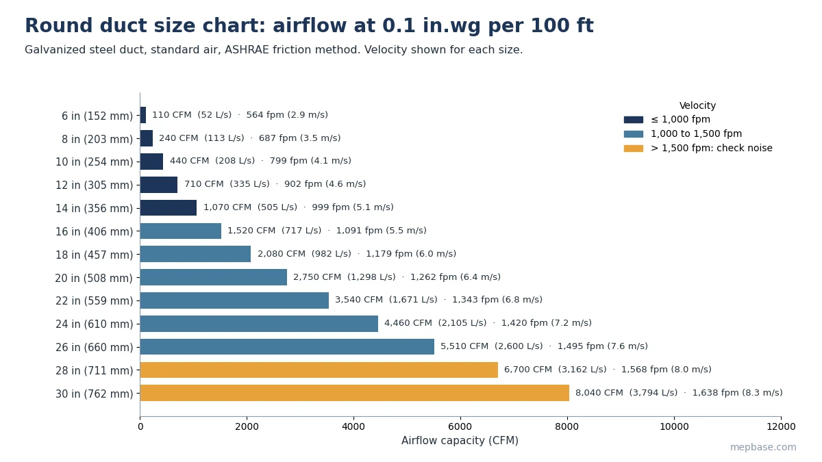
For large ducts, velocity at 0.1 in.wg climbs above 1,500 fpm, so mains near noise-sensitive rooms are often sized at a lower friction rate. For the difference between the two sizing approaches, see Equal Friction vs Velocity Method.
Rectangular to Round Duct Size Chart
Rectangular ducts are converted to an equivalent round diameter that gives the same friction loss at the same airflow, using the Huebscher formula:
De = 1.30 × (a × b)0.625 / (a + b)0.25
Where a and b are the duct width and height. Common sizes:
| Rectangular size (in) | Approx. size (mm) | Equivalent round (in) | CFM at 0.1 in.wg/100 ft | Aspect ratio |
|---|---|---|---|---|
| 8 × 6 | 200 × 150 | 7.6 | 210 | 1.3 : 1 |
| 10 × 8 | 250 × 200 | 9.8 | 410 | 1.3 : 1 |
| 12 × 8 | 300 × 200 | 10.7 | 520 | 1.5 : 1 |
| 12 × 10 | 300 × 250 | 12.0 | 700 | 1.2 : 1 |
| 16 × 10 | 400 × 250 | 13.7 | 1,020 | 1.6 : 1 |
| 16 × 12 | 400 × 300 | 15.1 | 1,310 | 1.3 : 1 |
| 20 × 12 | 500 × 300 | 16.8 | 1,730 | 1.7 : 1 |
| 24 × 12 | 600 × 300 | 18.3 | 2,170 | 2 : 1 |
| 20 × 16 | 500 × 400 | 19.5 | 2,580 | 1.3 : 1 |
| 24 × 16 | 600 × 400 | 21.3 | 3,260 | 1.5 : 1 |
| 30 × 16 | 750 × 400 | 23.7 | 4,300 | 1.9 : 1 |
| 24 × 20 | 600 × 500 | 23.9 | 4,420 | 1.2 : 1 |
| 30 × 20 | 750 × 500 | 26.6 | 5,880 | 1.5 : 1 |
| 36 × 20 | 900 × 500 | 29.0 | 7,370 | 1.8 : 1 |
| 40 × 24 | 1000 × 600 | 33.6 | 10,840 | 1.7 : 1 |
Keep the aspect ratio (width to height) at 3:1 or less where possible and never above 4:1. Flat, wide ducts use more sheet metal and have higher friction for the same airflow.
Recommended Duct Velocities
| Duct section | Commercial (fpm) | Commercial (m/s) | Residential (fpm) |
|---|---|---|---|
| Main supply duct | 1,000 to 1,500 | 5.0 to 7.5 | 700 to 900 |
| Branch supply duct | 600 to 900 | 3.0 to 4.5 | 500 to 600 |
| Main return duct | 800 to 1,200 | 4.0 to 6.0 | 600 to 700 |
| Branch return duct | 500 to 700 | 2.5 to 3.5 | 400 to 500 |
Use the lower end of each range near noise-sensitive spaces such as bedrooms, meeting rooms and studios.
How to Read the Duct Size Chart
- Find the airflow (CFM or L/s) for the duct section from your load calculation or diffuser schedule.
- In the round duct table, pick the smallest size whose capacity covers that airflow.
- Check the velocity against the recommended range for that section.
- If a round duct doesn’t fit the ceiling space, choose a rectangular size with the same or larger equivalent round diameter.
- Confirm the aspect ratio is 4:1 or less.
If you need the airflow first, start with the HVAC Load Calculation Guide.
Who Should Use This?
- HVAC designers and draftsmen
- Mechanical engineers and consultants
- Contractors and site supervisors
- Engineering students
Why Use a Duct Size Chart?
- Save time during design and coordination
- Quickly check compatible sizes for airflow needs
- Standardized references for submittals
- Avoid over- or under-sizing of ductwork
Download Duct Size Chart PDF
Click below to download the PDF chart. The link will appear after a short wait:
Checking…
Related Duct Sizing Tools and Guides
Need to calculate duct size live instead of reading a static chart?
- Online Ductulator: size round and rectangular ducts by friction rate or velocity
- Duct Calculator: quick air duct size from CFM
- Duct Friction and Velocity Calculator
- McQuay Duct Sizer Free Download
- External Static Pressure (ESP) Calculation: what the fan needs once ducts are sized
Frequently Asked Questions
What size duct do I need for 1,000 CFM?
At 0.1 in.wg per 100 ft, a 14 in (356 mm) round duct carries about 1,070 CFM at roughly 1,000 fpm. A 16 × 10 in rectangular duct is a common equivalent.
What friction rate is used in a duct size chart?
Most low-pressure comfort systems are sized at 0.08 to 0.10 in.wg per 100 ft (0.65 to 0.8 Pa/m). This chart uses 0.1 in.wg per 100 ft.
How do I convert a rectangular duct to round?
Use the equivalent diameter formula De = 1.30 × (a × b)0.625 / (a + b)0.25, or read it from the rectangular to round table above.
What is the maximum aspect ratio for rectangular ducts?
Keep it at 3:1 or less where possible, and no more than 4:1.
Final Thoughts
This Duct Size Chart PDF makes ductwork design easier and faster, especially during BOQ takeoffs, site inspections, or quick revisions. Keep it printed or saved on your device for instant reference.
Visit MEPBase.com for more MEP resources, tools, and drafting support.
need duct calculator
https://mepbase.com/mcquay-duct-sizer-free-download/