Air Handling Unit (AHU) Installation Detail DWG Free Download
Downloadable AutoCAD block for a typical roof-mounted Air Handling Unit (AHU) installation — covering the unit’s internal component layout, the concrete housekeeping pad, vibration isolation and the roof curb waterproofing detail. Free for personal and professional use.
What’s in the Drawing
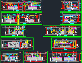
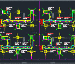
The block contains three views:
- AHU Installation Detail — full elevation showing the internal component train, from return air intake to supply air discharge
- Typical AHU Concrete Pad Detail — the unit mounted on its housekeeping pad, vibration isolators and anchor bolt callout
- Detail (1) — AHU Installation Detail on Roof — a zoomed section through the isolator-to-pad connection, specifically for roof-mounted units
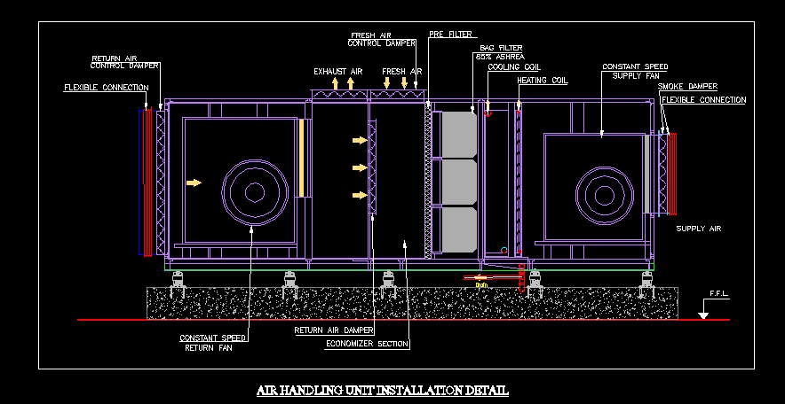
AHU Component Breakdown (Elevation)
This is a draw-through configuration — the supply fan sits after the coils, pulling air through them rather than pushing it. This gives more even air velocity across the coil face and reduces the risk of condensate carryover into the ductwork, which is why it’s the standard arrangement for central-station AHUs.
Reading the airflow path left to right:
| Component | Function |
|---|---|
| Return Air Control Damper + Flexible Connection | Modulates return airflow into the unit; the flexible connection isolates fan vibration from the return ductwork |
| Constant Speed Return Fan | Draws return air from the space back into the AHU |
| Return Air Damper + Economizer Section | Mixing box — blends return air with fresh/exhaust air; the economizer section allows free cooling using outdoor air when conditions permit |
| Exhaust Air Damper & Fresh Air Control Damper | Reject a portion of return air while drawing in fresh outdoor air at a controlled ratio |
| Pre-Filter | First-stage filtration — protects the finer bag filter and coils from coarse dust |
| Bag Filter, 85% ASHRAE | Second-stage filtration rated to ASHRAE 52.1 dust-spot efficiency — a mid-to-high efficiency bag filter typical of commercial HVAC (roughly in the MERV 13–14 range) |
| Cooling Coil | Chilled-water or DX coil — the main sensible + latent cooling stage |
| Heating Coil | Hot-water or electric reheat coil, downstream of cooling |
| Constant Speed Supply Fan | Discharges conditioned air into the supply ductwork |
| Smoke Damper + Flexible Connection | Closes on fire/smoke detection to isolate the AHU from the duct system; flexible connection isolates supply-side vibration |
The unit sits on a concrete housekeeping pad with spring-type vibration isolators at each support point, with F.F.L. (Finished Floor Level) called out for coordination with the structural drawings.
Concrete Pad & Vibration Isolation
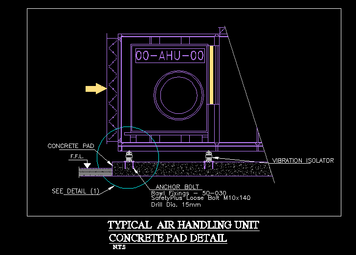
The unit (tagged 00-AHU-00 — replace with your project’s actual equipment tag) sits on a concrete pad raised above the finished floor level, isolated from the structure by spring vibration isolators anchored through the pad. The drawing calls out the fixing:
Sizing the isolators and the pad correctly matters: an AHU’s rotating fans generate vibration that, without isolation, transmits through a rigid connection straight into the building structure — heard and felt as low-frequency hum or rattle in occupied spaces below or adjacent to plant rooms and roof-mounted units.
Roof Curb Detail — Detail (1)
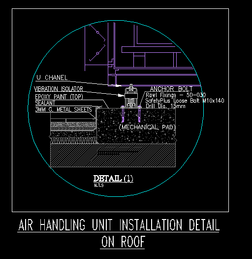
This is the zoomed section (circled as “See Detail (1)” on the pad drawing above), specific to a roof-mounted installation. Beyond structural support and vibration isolation, a roof curb has one more job: keeping water out of the building at the point where the unit penetrates the roof. The detail calls out:
- U-Channel — structural mounting channel carrying the isolator and unit base rail
- Vibration Isolator — spring mount, same anchor bolt spec as the pad detail above
- Epoxy Paint (Top) — protective/waterproof coating on the mechanical pad surface
- Sealant — perimeter seal at the pad/curb joint
- 3 mm G. Metal Sheets — galvanized metal flashing/cladding around the curb
- (Mechanical Pad) — the concrete curb itself, built up on the roof structure
A roof curb is one of the most common sources of roof leaks on commercial buildings when detailed poorly — the combination of sealant, epoxy coating and galvanized flashing shown here is standard practice for keeping the roof membrane watertight around the penetration while still allowing the isolators to do their job.
Why These Details Matter
- Flexible connections at both return and supply openings stop fan vibration from traveling down the ductwork and radiating noise through the whole system — not just at the unit itself.
- Draw-through fan placement (after the coils) gives more uniform face velocity across the cooling coil, which improves dehumidification performance and reduces condensate carryover risk compared to blow-through arrangements.
- Pre-filter + bag filter staged filtration protects the coil surfaces from fouling and extends the life of the more expensive bag filter — replace the pre-filter far more often than the bag filter.
- Vibration isolators sized to the unit’s operating weight (not just its shipping weight) are what actually prevent structure-borne noise — undersized springs are one of the most common rooftop AHU commissioning complaints.
- Roof curb waterproofing (sealant + flashing + coating) is not optional detailing — it is what stands between a rooftop mechanical installation and a ceiling leak two floors down.
Checking…
FAQ
What does “85% ASHRAE” filter rating mean?
It refers to the dust-spot efficiency test method under ASHRAE Standard 52.1 — an 85% dust-spot efficiency bag filter is a mid-to-high efficiency filter commonly used in commercial HVAC, roughly comparable to the MERV 13–14 range under the newer MERV rating system.
What is a draw-through AHU configuration?
A layout where the supply fan is positioned after the cooling and heating coils, pulling air through them rather than pushing it. It gives more even airflow across the coil face and lowers the risk of moisture carryover downstream, and is the standard configuration for central-station AHUs.
Why do AHUs need vibration isolators?
Fans and motors generate vibration at their rotating frequency; without isolation, a rigid mounting transmits that vibration directly into the building structure, which is heard as hum or felt as rattle in spaces below or beside the plant room or roof unit. Spring isolators absorb that energy before it reaches the structure.
What is a roof curb and why does it need flashing and sealant?
A roof curb is the raised structural/concrete base that a rooftop unit sits on, built up through the roof membrane. Sealant, waterproof coating and metal flashing around the curb keep water from tracking down the penetration into the building — a poorly detailed curb is one of the most common causes of roof leaks under rooftop mechanical equipment.
What anchor bolts are specified for the vibration isolators?
The drawing calls out Rawl Fixings 5D-030, SafetyPlus loose-bolt M10 × 140, with a 15 mm drill diameter — confirm this against your isolator manufacturer’s load rating and your local structural engineer’s approval before installation.
Final Thoughts
Download the block, adjust the equipment tag, dimensions and anchor bolt spec to your project, and route it through your structural engineer for the roof loading and fixing approval. For more HVAC AutoCAD blocks, downloads and free calculators, stay tuned with MEPBase.com.
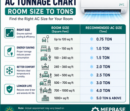
Related tools: size the unit’s cooling capacity with our AC Tonnage Calculator, convert to airflow with the TR to CFM Calculator, and check coil condensation risk with the Dew Point Calculator.