Chilled Water Pipe Sizing: Standard, Chart & Free Calculator
Sizing chilled water (CHW) pipes correctly is one of the highest-impact decisions in any hydronic HVAC design. The pipe diameter sets your pump energy, your noise levels, and a big slice of your installation cost. This guide gives you the chilled water pipe sizing standard the industry actually uses (ASHRAE and Carrier), a ready-to-use pipe size chart, a free Excel sheet and online calculator, and a clear step-by-step method you can trust on real projects.
Want the tools right away? Grab the free Excel download or open the online CHW pipe calculator. Both are free, with no email and no paywall.
What Is Chilled Water Pipe Sizing?
Chilled water pipe sizing is the process of choosing the pipe diameter that carries the required flow from the chiller to the air handling units and fan coil units, while keeping velocity and friction loss (pressure drop) within accepted limits.
Three numbers decide the answer:
- The flow rate required, set by the cooling load (in GPM or L/s).
- The velocity you allow, to control noise and pipe erosion.
- The friction loss you accept per 100 ft of pipe, which drives pump head and running cost.
A good calculator balances all three so the pipe is neither starved nor wasteful.
Why Correct CHW Pipe Sizing Matters
- Pump energy. Friction rises roughly with the square of velocity, so one size too small can sharply increase pump power for the same flow.
- Noise. High velocity, especially at valves, sharp turns, and size reductions, creates flow noise that carries into occupied spaces.
- Erosion. Sustained high velocity erodes pipe walls and fittings, shortening system life.
- Capital cost. Oversized pipe, insulation, hangers, and valves cost more and eat into tight ceiling space.
Chilled Water Pipe Sizing Standard (ASHRAE & Carrier)
Most engineers size chilled water pipes against a well-known rule of thumb drawn from ASHRAE and Carrier guidance.
| Pipe Size | Sizing Basis |
|---|---|
| 2″ and below (50 mm and below) | Velocity limit of 4 fps (1.2 m/s) |
| Above 2″ (above 50 mm) | Friction loss limit of 4 ft per 100 ft (about 400 Pa/m) |
In other words, small pipes are limited by velocity and larger pipes by friction loss. Beyond this rule of thumb, there are hard outer limits you should never cross:
- Velocity: minimum 2 fps (0.6 m/s), maximum 15 fps (4.6 m/s).
- Friction loss: minimum 0.75 ft per 100 ft, maximum 10 ft per 100 ft (about 1000 Pa/m).
The minimum velocity of 2 fps matters because chilled water must move fast enough to carry entrained air bubbles to the air vents; too slow and air pockets hurt the heat transfer at the coils. The maximum velocity guards against erosion, which becomes significant above roughly 10 fps and is capped at 15 fps for any service.
Chilled Water Pipe Size Chart
The chart below applies the standard directly: pipes 2″ and smaller are sized to 4 fps, and pipes above 2″ are sized to 4 ft/100 ft friction loss (Schedule 40 steel, chilled water).
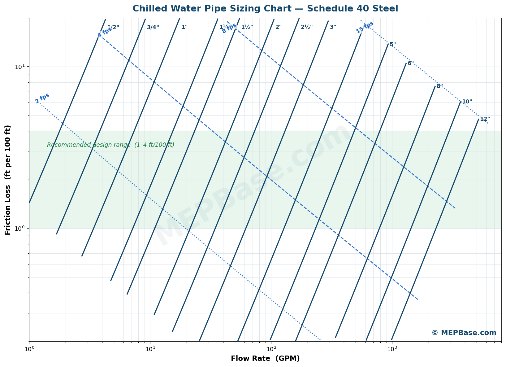
Use the table for a fast first pick, then confirm with the calculator.
| Nominal Size | Sizing Basis | Max Flow (GPM) | Max Flow (L/s) | Velocity (fps) |
|---|---|---|---|---|
| 1/2″ | 4 fps | 4 | 0.2 | 4.0 |
| 3/4″ | 4 fps | 7 | 0.4 | 4.0 |
| 1″ | 4 fps | 11 | 0.7 | 4.0 |
| 1 1/4″ | 4 fps | 19 | 1.2 | 4.0 |
| 1 1/2″ | 4 fps | 25 | 1.6 | 4.0 |
| 2″ | 4 fps | 42 | 2.6 | 4.0 |
| 2 1/2″ | 4 ft/100 ft | 73 | 4.6 | 4.9 |
| 3″ | 4 ft/100 ft | 130 | 8.2 | 5.7 |
| 4″ | 4 ft/100 ft | 268 | 16.9 | 6.7 |
| 5″ | 4 ft/100 ft | 487 | 30.7 | 7.8 |
| 6″ | 4 ft/100 ft | 791 | 49.9 | 8.8 |
| 8″ | 4 ft/100 ft | 1629 | 102.8 | 10.4 |
| 10″ | 4 ft/100 ft | 2963 | 186.9 | 12.1 |
| 12″ | 4 ft/100 ft | 4755 | 300.0 | 13.5 |
Notice how velocity stays well under the 15 fps ceiling across the whole range, and how larger pipes naturally run faster while holding the same friction rate. To read the chart above: find your flow on the bottom axis, go up to the pipe-size line, then check the friction loss (left axis) and velocity (blue lines). Keep your point inside the green design band.
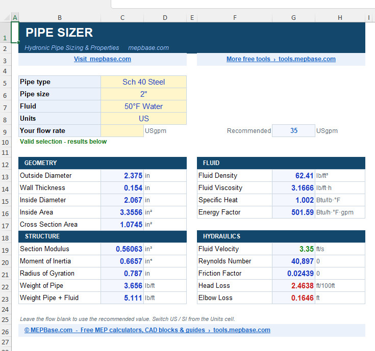
Free Chilled Water Pipe Sizing Excel
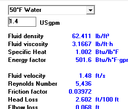
We have packaged the full method into a clean, ready-to-use spreadsheet. Choose the pipe type, size, and fluid, enter your flow, and it returns velocity, Reynolds number, friction factor, head loss, elbow loss, and complete pipe properties, in US or SI units.
Checking…
No sign-up, no email, no paywall, just download and use it. The Excel sheet is perfect for desk checks, site verification, and learning, and it complements the online calculators below.
Online Chilled Water Pipe Calculator
Prefer instant results in the browser? Use either tool:
- Chilled Water Pipe Calculator – size CHW pipes by flow, velocity, and friction.
- CHW Pipe Calculator – a fast alternative interface for the same job.
Both run the same engineering logic as the Excel sheet, so your desk check and your field check will always agree.
How to Size a Chilled Water Pipe (Step by Step)
- Find the design flow. Convert the cooling load to GPM (or L/s) using your design temperature difference. A common CHW design uses a 10°F (about 5.5°C) delta-T, which gives roughly 2.4 GPM per ton.
- Apply the standard. For pipes 2″ and below, target 4 fps; for pipes above 2″, target 4 ft/100 ft.
- Pick a trial size from the pipe size chart above.
- Check velocity and friction for that size with the calculator. If either exceeds your target, go up one size; if both are very low, you may be able to go down a size.
- Repeat for each segment. Mains carry more flow than branches, so the diameter steps down toward the terminals.
- Confirm pump head. Add the friction of the longest (index) run plus fittings and equipment to set the pump duty.
As a worked example, a 4″ pipe carrying 200 GPM gives about 5 fps and roughly 2.3 ft/100 ft, which is comfortably inside the standard, so 4″ is suitable for that flow.
Recommended Velocity by Service (Carrier)
The single 4 fps / 4 ft/100 ft rule of thumb is a starting point. In practice, Carrier recommends different velocity bands for different parts of the system, balancing erosion and noise.
| Service | Recommended Velocity (fps) |
|---|---|
| Pump discharge | 8 – 12 |
| Pump suction | 4 – 7 |
| Header | 4 – 15 |
| Riser | 3 – 10 |
Erosion also depends on how many hours per year the system runs. Carrier ties the maximum velocity to operating hours: heavily used pipes (around 8000 hr/year) should stay near 8 fps, while lightly used pipes (around 1500 hr/year) can tolerate up to 15 fps. Pump suction should be kept lower to protect against cavitation. Many engineers size most chilled water pipes around 9 to 10 fps, always keeping velocity above 2 fps and below 15 fps.
Friction Loss and the Cost Trade-Off
Friction loss (also called pressure drop or head loss) is the second pillar of pipe sizing, and it is really a cost decision:
- Lower friction loss means a bigger pipe: higher material, insulation, and labour cost, but lower pump energy for the life of the system.
- Higher friction loss means a smaller pipe: cheaper to install, but more pump energy every year.
Because the cost difference between small pipe sizes is modest, it pays to size small pipes (below 4″) to a lower friction loss to save pumping energy. For large pipes (4″ and above), the material and insulation cost climbs steeply, so a higher friction loss is more economical. Carrier notes that in large air-conditioning systems, the cost balance point is often taken at a maximum of about 10 ft/100 ft.
Two more practical factors push toward smaller pipe where possible: large pipes are harder to handle on site (often needing lifting tools), and ceiling space above the slab is frequently too tight for very large diameters. On the other hand, an owner-operated building often justifies a lower friction loss (bigger pipe), since the energy savings benefit the owner for years.
Pipe Material and Schedule
Steel (Schedule 40), copper (Type K, L, M), and plastics (PVC, ABS) have different internal diameters and roughness for the same nominal size, so the same flow gives a slightly different velocity and friction in each. A proper calculator lets you select the exact material and schedule rather than assuming one, which is why our Excel sheet and online tools include all of them.
McQuay Pipe Sizer (Free Download)
If you prefer the classic McQuay (now Daikin Applied) pipe sizer workflow, we host a free version with a full write-up here: McQuay Pipe Sizer – Free Download. It is a great companion to the chilled water tools on this page and uses the same core hydraulic principles.
Common Chilled Water Pipe Sizing Mistakes
- Ignoring the standard and sizing only to “what fits the flow,” which leads to inconsistent pump head.
- Using one velocity limit everywhere. Suction, discharge, headers, and risers each have their own recommended band.
- Dropping below 2 fps, which lets air pockets collect and hurts coil performance.
- Forgetting fittings. Elbows, tees, and valves add the equivalent of many metres of straight pipe.
- Mixing up material schedules. Sch 40, Sch 80, and copper Type L have different internal diameters for the same nominal size.
Frequently Asked Questions
What is the chilled water pipe sizing standard?
The common rule of thumb from ASHRAE and Carrier is a velocity limit of 4 fps for pipes 2″ and below, and a friction loss limit of 4 ft per 100 ft for pipes above 2″. The absolute limits are 2 to 15 fps for velocity and 0.75 to 10 ft per 100 ft for friction loss.
What velocity is recommended for chilled water pipes?
Keep velocity between 2 fps (minimum, to carry air) and 15 fps (maximum, to limit erosion). Carrier suggests roughly 8-12 fps for pump discharge, 4-7 fps for pump suction, 4-15 fps for headers, and 3-10 fps for risers.
How do I calculate chilled water pipe size?
Start from the design flow, apply the standard (4 fps for 2″ and below, 4 ft/100 ft for above 2″), pick a trial size from the chart, then confirm velocity and friction with a calculator and adjust the size up or down.
What friction loss should I use for chilled water?
Stay within 0.75 to 10 ft/100 ft. Use a lower friction loss for small pipes (below 4″) to save pump energy, and a higher friction loss for large pipes (4″ and above) to save installation cost, with about 10 ft/100 ft as a common upper balance point.
Can I size chilled water pipes in Excel?
Yes. Our free CHW pipe sizing Excel lets you select pipe material, schedule, size, and fluid, then returns velocity, friction loss, and full pipe properties in US or SI units, with no email or paywall.
What is the McQuay pipe sizer?
The McQuay pipe sizer is a long-standing tool for hydronic pipe sizing. You can get our free version and guide on the McQuay Pipe Sizer page.
Conclusion
Good chilled water pipe sizing is about balancing velocity, friction, and cost against a clear standard, not just finding a pipe that carries the flow. Apply the 4 fps / 4 ft/100 ft rule of thumb, respect the 2-15 fps and 0.75-10 ft/100 ft outer limits, use the chart for a fast first pick, and confirm every segment with a calculator.
Get started now: download the free Chilled Water Pipe Sizing Excel, or run the numbers instantly in the online CHW pipe calculator. For more free MEP calculators, CAD blocks, and guides, explore MEPBase.com.