Fire Pump Room DWG Free Download — Complete Layout, Sections, Isometric & NFPA 20 Details
A fire pump room shop drawing is one of the hardest MEP drawings to produce from scratch: suction from the water tank, pump alignment, discharge manifold, alarm valve bank, test line back to the tank, sensing lines, control panels and every support — all coordinated in one room. This fire pump room DWG, taken from a real approved project, gives you the complete package ready to adapt: layout plan, three sections, tank connection detail, full isometric with valve schedule, control panel dimensions, NFPA 20 sensing line detail and pipe support details — free to download at the end of this post.
What’s Included in the Fire Pump Room DWG?
- Pump room layout plan (plan view with all piping, dimensions and BOP levels)
- Sections A-A, B-B, C-C and tank connection Section D-D
- Isometric view of the complete pump room with an 11-item valve and fittings schedule
- Control panel dimensional details (2 electric pump sets, jockey set and ATS)
- Pressure sensing line detail per NFPA 20
- Pipe support details: wall mounted, floor mounted (height adjustable), channel supports and sensing line supports
Fire Pump Room Layout Plan
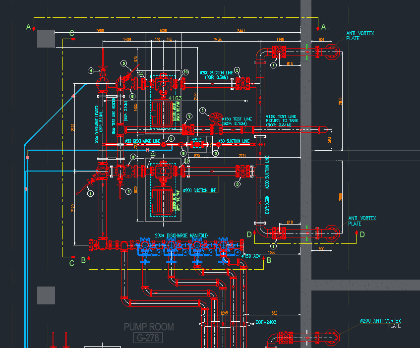
The plan shows a pump set drawing from the fire water tank through two Ø200 suction lines (BOP 0.38 m), each terminating in the tank with an anti-vortex plate. The jockey pump takes a separate Ø50 suction. Discharge collects in a Ø200 discharge manifold feeding the alarm valve bank, with a Ø150 automatic control valve (ACV) and a Ø150 test line returning to the tank (BOP 2.10 m rising to 3.81 m) so the pumps can be flow-tested without wasting water. Every run is dimensioned and level-tagged — exactly what a consultant expects on a pump room submittal.
Isometric View with Valve Schedule
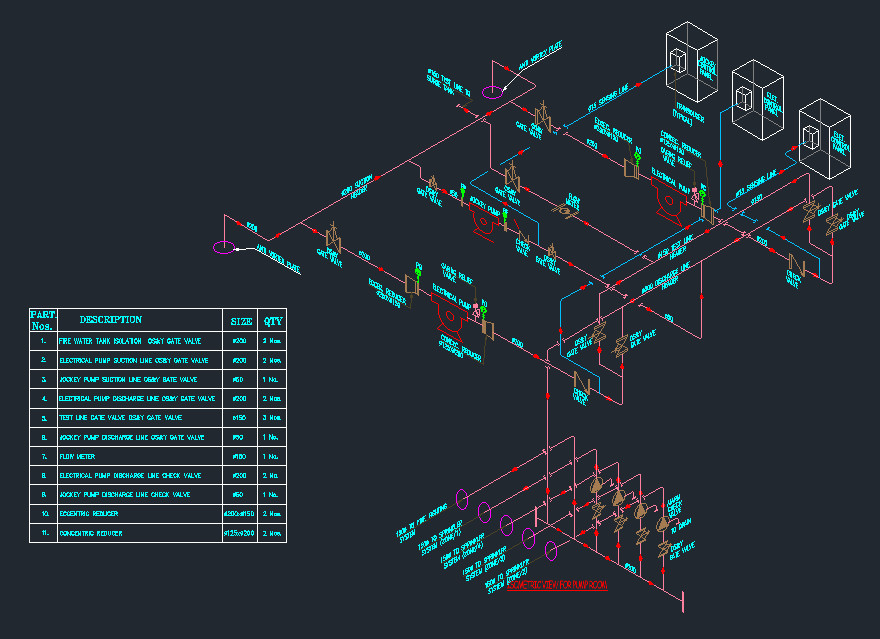
The isometric ties the whole room together and is keyed to an 11-item schedule — the fastest way to build your valve material take-off:
- Ø200 O.S.&Y. gate valves — tank isolation (2), pump suction (2) and pump discharge (2)
- Ø50 O.S.&Y. gate valves — jockey suction and discharge
- Ø150 gate valves on the test line (3) with a Ø150 flow meter
- Ø200 check valves on the electric pump discharge (2) and a Ø50 check valve on the jockey discharge
- Eccentric reducer 200×150 on suction and concentric reducers 125×200 on discharge — eccentric on suction keeps the pipe crown flat and prevents air pockets
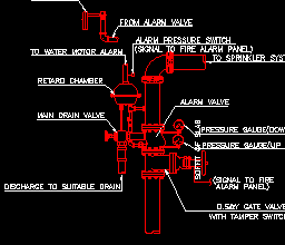
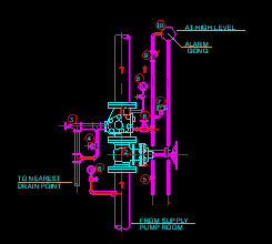
The isometric also shows the sensing lines running from the discharge header to the transducers of each controller — with the tank fill, drain connections and distribution to four sprinkler zones and the wet riser.
Pump Room Sections (A-A, B-B, C-C)
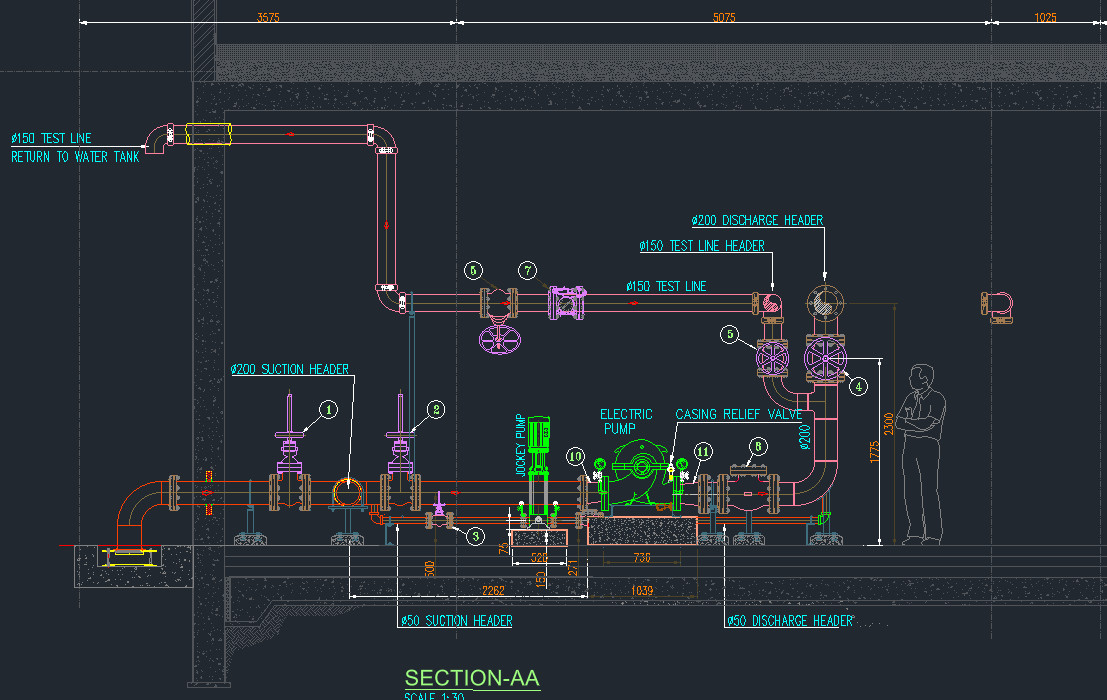
Section A-A (shown above) cuts through the pump train: the Ø200 suction header with O.S.&Y. valves on housekeeping pads, the vertical jockey pump, the horizontal split-case electric pump with its casing relief valve, rising into the Ø200 discharge header and Ø150 test line header at 2300 mm, with the test line returning to the water tank. Pump pads are dimensioned (approx. 730 mm for the main pump, 520 mm for the jockey, 150 mm high).
The other two sections complete the picture. Section B-B shows the alarm valve bank: four alarm check valves at 750 mm spacing on the Ø200 manifold, each with its Ø15 line to the alarm gong, feeding Ø150 SRP risers to sprinkler zones 1–4 plus a Ø150 WRP to the wet riser / fire fighting system (BOP 2400 mm, room clear height 4500 mm, drains piped to the nearest drain point). Section C-C shows the two electric pump sets side by side (1825 mm pads) with the jockey between them (480 mm pad), and Section D-D details the tank wall crossing: puddle flange through the concrete wall, 600 mm stub, isolation valve and the anti-vortex plate at the tank floor.
Control Panels & ATS
The DWG includes dimensioned elevations and side views for all controllers: two electric-driven pump controllers (610 × 1372 × 363 mm), a jockey pump controller (305 × 305 × 200 mm) and the automatic transfer switch (ATS) — each wall-mounted with its transducer, sensing line inlet, ball valve and drain. Electrical coordination is covered too: panel wall space is dimensioned in section (electric panels 800 × 1500 × 350 mm, jockey panel 305 × 305 × 200 mm) so the electrical contractor knows exactly what to reserve.
Pressure Sensing Line Detail (NFPA 20)
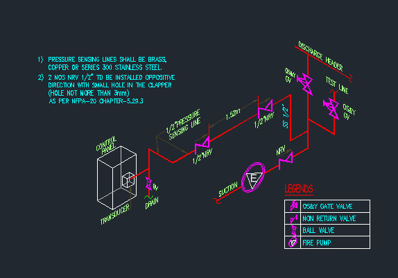
The detail every civil defense inspector checks. Per NFPA 20, each sensing line runs from the discharge side to its controller and must include:
- Piping in brass, copper or Series 300 stainless steel — never black steel
- Two ½” non-return valves installed at least 5 ft (1.52 m) apart, mounted in the opposite direction of flow, each with a nominal 2.4 mm (3/32″) hole drilled in the clapper (not more than 3 mm) to act as pressure dampening
- A ball valve and drain at the controller/transducer end for testing
The DWG also includes a ground-level support detail for the Ø15 sensing lines (U-bolts on a common base at EL +0.10 m) — a small detail that keeps sensing lines from being kicked or crushed in the pump room.
Pipe Support Details
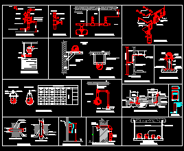
Two full sheets of supports are included so nothing is left “by contractor”: wall-mounted type (100 × 50 steel channel, M10 galvanized anchor bolts with plate washers, M10 threaded U-bolts, pipe hanger on all-thread rod, and a 75 × 75 × 8 mm angle bracket option) and floor-mounted type (height-adjustable stand on M16 continuous threaded rods with 10 mm thick G.I. plates and housekeeping pads, plus U-channel supports for pipe pairs at 450 mm centers).
How to Adapt This Pump Room DWG to Your Project
Update the pipe sizes and pump pads to match your hydraulic calculation and approved pump submittal, verify sensing line routing against your controller supplier’s manual, and re-check zone counts on the alarm valve manifold. For the electrical side, size the pump feeders and panel with our Electrical Panel Load Calculator and check motor power factor correction with the Power Factor Calculator. You can also grab our companion set of 19 fire fighting CAD details (free download) — sprinkler, deluge, hydrant and support details that pair perfectly with this pump room drawing.
Free Download — Fire Pump Room DWG
The complete drawing — layout plan, all sections, isometric with schedule, control panels, NFPA 20 sensing line detail and pipe supports — in a single AutoCAD file. Free for personal and professional use; a link back to MEPBase is appreciated.
Checking…
Frequently Asked Questions
Is this fire pump room DWG really free to download?
Yes. The complete DWG — layout, sections, isometric, control panels and support details — is free to download and use in your projects, with no registration required.
What pumps does the drawing show?
The arrangement shows two electric-driven fire pump sets with an automatic transfer switch and a vertical multistage jockey pump, drawing from a fire water tank through Ø200 suction lines with anti-vortex plates. If your project uses a diesel standby pump instead of the second electric set, replace that train and its controller accordingly.
Why must the suction reducer be eccentric?
An eccentric reducer installed flat-side-up keeps the top of the suction pipe level, so no air pocket can form ahead of the pump impeller. A concentric reducer on suction traps air and can cause cavitation and loss of prime — which is why the schedule specifies eccentric on suction and concentric on discharge.
What does NFPA 20 require for the pressure sensing line?
Each pump controller gets its own sensing line in brass, copper or Series 300 stainless steel, with two ½” check valves at least 5 ft (1.52 m) apart installed against the flow direction, each with a nominal 2.4 mm (3/32″, max 3 mm) hole drilled in the clapper for dampening.
What is the test line in the pump room for?
The Ø150 test line with its flow meter lets you run the annual full-flow test of the fire pumps and return the water to the tank instead of dumping it to drain — a standard requirement where water is scarce or discharge to drainage is restricted.
Can I use this drawing for my shop drawing submittal?
Yes — that is its purpose. Insert it in your title block, update sizes and levels to match your design, and coordinate with your approved pump, controller and valve submittals before submission.