Typical Detail for External Network Manholes & Underground Water Pipes – DWG Free Download
Planning underground utility networks requires precise construction details to ensure durability, safety, and long-term performance. This Typical Detail for External Network Manholes & Underground Water Pipes (Fire Fighting / Irrigation / Water Supply) DWG provides a complete technical reference for installing underground water infrastructure in residential, commercial, and industrial projects.
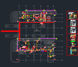
Typical Detail for External Network Manholes DWG Free Download
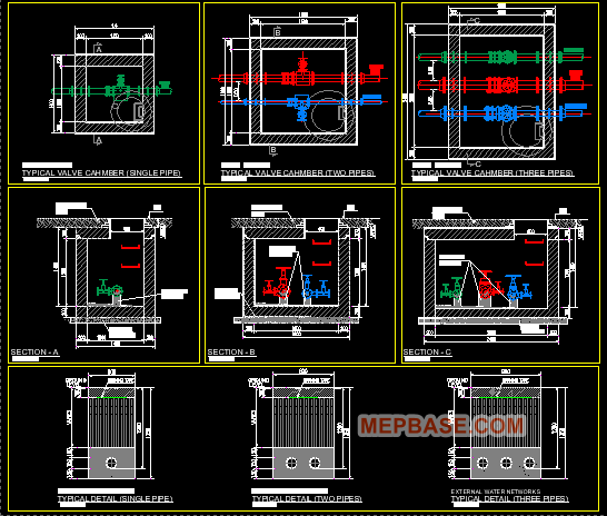
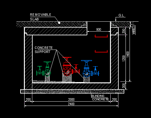
This AutoCAD DWG file presents a sectional detail of an RCC manhole or valve chamber connected to underground water pipelines. It clearly illustrates construction layers, pipe positioning, and structural components required for proper installation.
The drawing is suitable for:
- Fire Fighting Underground Networks
- Irrigation Water Distribution Systems
- Domestic Water Supply Pipelines
It can be used for shop drawings, project submissions, and on-site execution guidance.
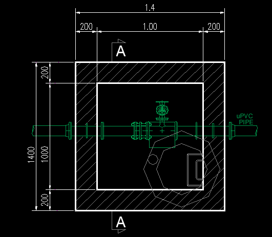
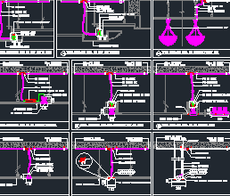
Manhole / Valve Chamber Construction Detail
The DWG includes a reinforced cement concrete (RCC) manhole section showing:
- RCC base slab and side walls
- Internal plastering or waterproofing finish
- Heavy-duty ductile iron cover and frame
- Defined internal clearance for valve operation
Proper chamber construction ensures safe access for maintenance, inspection, and valve control.
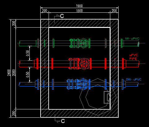
Underground Water Pipe Installation Detail
The drawing clearly indicates:
- Pipe diameter (DN size)
- Invert Level (IL)
- Finished Ground Level (FGL)
- Pipe penetration through chamber walls
It also shows the recommended installation depth to protect pipelines from external loads and surface activities.
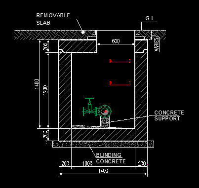
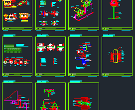
Pipe Bedding and Backfilling Requirements
Correct bedding and backfilling are essential for pipeline stability. The DWG typically includes:
- 100–150 mm sand bedding below the pipe
- Selected backfill material around the pipe
- Layer-by-layer compaction
- Warning tape above pipeline level
These measures prevent settlement, leakage, and structural damage over time.
Fire Fighting System Considerations
For fire fighting networks, the drawing includes thrust block details at bends and fittings to resist hydraulic pressure forces. Isolation valves and access arrangements are integrated within the chamber for operational safety.
Applications and Usage
This DWG is ideal for:
- Civil and infrastructure projects
- Landscaping and irrigation works
- Residential compounds
- Commercial and industrial developments
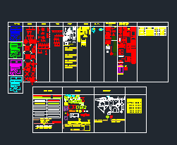
File Format: AutoCAD DWG (Editable)
Purpose: Construction reference and engineering documentation
Before execution, always verify pipe sizes, concrete grades, reinforcement details, and compaction standards as per project specifications and local authority requirements.
Download Typical Detail for External Network Manholes