AutoCAD Exit Signs — 30+ Free DWG Blocks (ISO 7010) with Sizing & Placement Guide
Drawing an evacuation plan or an emergency lighting layout and need AutoCAD exit signs that actually look right on paper? This free DWG library contains 30+ exit sign CAD blocks — ISO 7010 running-man pictograms, every arrow direction, “Fire exit” and “Exit” text variants, “Fire exit — Keep clear” door signs and standalone directional arrows — all drawn in the correct green-and-white safety colours and ready to insert.
But a block library alone doesn’t get a drawing approved. So below the download you’ll also find the part most CAD block sites skip: which ISO code each symbol carries, how to size a sign for its viewing distance, where the codes require signs to be placed, and how to set the blocks up in AutoCAD so they plot correctly at every scale.
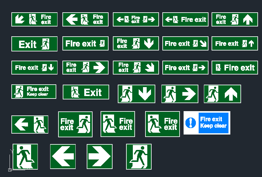
What’s Included in the Exit Sign DWG
| Block Group | Variants Included | Typical Use |
|---|---|---|
| Running man + arrow (rectangular) | Left, right, up, down, and all four diagonals | Corridor and escape route direction |
| “Fire exit” text signs | Text left or right of pictogram, with or without arrow | Above exit doors, stair lobbies |
| “Exit” text signs | Short-text versions, both pictogram orientations | Where local practice uses “Exit” only |
| “Fire exit — Keep clear” | Green safety version and blue mandatory version | On the exit door leaf itself |
| Square pictogram only | Running man left / right, no text | Small plan-scale symbols, legends |
| Standalone arrows | Left, right, up, down in green panel | Supplementary route marking |
Which ISO 7010 Symbol Is Which?
If your drawing is reviewed against ISO or EN standards, the reviewer will look for the correct ISO 7010 reference code in your legend, not just a green box. The two you need most:
- E001 — Emergency exit (left hand): running man moving to the left
- E002 — Emergency exit (right hand): running man moving to the right
- Directional arrows (E005 / E006): supplementary arrows combined with E001/E002 to form a complete escape-route sign
Two rules that get flagged in review: the running man must face the same way the arrow points (a left-facing man with a right arrow is a genuine safety defect, not a drafting nitpick), and the pictogram should always sit on the side the person is travelling towards. The blocks in this file are already paired correctly — but if you mirror a block to flip its direction, check that the text hasn’t mirrored with it.
How Big Should an Exit Sign Be? (Viewing Distance Rule)
Sign size is not a style choice — it’s calculated from how far away it must be readable. The standard rule from ISO 3864-1 / EN 1838 is:
Viewing distance = Sign height × Distance factor
Distance factor = 100 for externally illuminated signs, 200 for internally illuminated (backlit) signs
| Sign height | Externally illuminated (×100) | Internally illuminated (×200) |
|---|---|---|
| 100 mm | 10 m | 20 m |
| 150 mm | 15 m | 30 m |
| 200 mm | 20 m | 40 m |
| 300 mm | 30 m | 60 m |
So a 150 mm high backlit sign covers a 30 m corridor; the same sign relying on ambient light only covers 15 m. Under US practice (NFPA 101 / IBC), the parallel requirement is written differently — letters at least 6 in (152 mm) high with a minimum 3/4 in (19 mm) stroke width, and no point in the exit access further than 100 ft (30 m) (or the sign’s listed viewing distance, whichever is less) from the nearest visible sign. Whichever code you work to, measure the longest sightline in each corridor before you fix the sign size.
Where to Place Exit Signs on Your Drawing
- Above every exit door and at every door in the means of egress that could be mistaken for an exit
- At every change of direction in a corridor, and at corridor intersections where the route isn’t obvious
- At stair landings, showing continuation up or down to the final exit discharge
- Mounting height: typically 2000–2500 mm above finished floor to the bottom of the sign, kept clear of ducts, ceiling bulkheads and open door swings — verify against your local civil defence or authority requirement
- Low-level signage: some occupancies (hotels, assembly, certain jurisdictions) additionally require signs near floor level, where smoke obscures ceiling-mounted signs
- Never place an exit sign where a fire door leaf, when open, hides it — a common coordination clash worth checking against the architectural door schedule
Remember that exit signage sits on the emergency circuit: signs and escape-route lighting must stay lit on loss of normal power for the code-required duration (commonly 90 minutes under NFPA 101/IBC, 1 hour minimum under EN 1838, with 3 hours often required in sleeping and high-risk occupancies).
Setting the Blocks Up in AutoCAD
A few minutes of setup saves hours of replotting:
- Insert into a dedicated layer — e.g.
E-LITE-EXITorFP-SIGN— so signage can be isolated for the fire-safety plan without carrying the whole electrical layout with it. - Make the blocks annotative. Select the block definition, set Annotative = Yes and add the scales you plot at (1:50, 1:100, 1:200). The symbol then stays the same size on paper regardless of viewport scale — far cleaner than keeping three scaled copies.
- Purge and audit after insertion (
PURGEthenAUDIT) to strip any layers riding along with the blocks. - Consider one dynamic block instead of thirty. Add a visibility parameter with states for each arrow direction, and you can flip a sign’s direction from the properties palette rather than erasing and re-inserting.
- Add them to a tool palette (
TOOLPALETTES) so the whole set is one drag away on every future project. - Build a legend listing each symbol with its ISO code, sign size and mounting height — the single fastest way to reduce consultant comments on a signage drawing.
Common Mistakes to Avoid
- Mirroring a block so the text reads backwards — use the arrow-direction variants provided instead of
MIRROR - Mixing “Exit” and “Fire exit” wording randomly across one building; pick one convention per project
- Sizing every sign the same regardless of corridor length
- Showing signs on the plan but forgetting the circuit, so the electrical drawing and the fire-safety plan disagree
- Placing the “Keep clear” sign on the wall instead of on the door leaf where it belongs
Free Download — AutoCAD Exit Signs DWG
All blocks in one AutoCAD file, purged and layer-organised, in metric units. Free for personal and professional use — no registration required.
⬇ Download AutoCAD Exit Signs (DWG) — Free
File format: DWG | Blocks: 30+ | Units: Metric | Price: Free
Related Free Resources
Pair these signs with our 19 fire fighting CAD details (free DWG) and the complete fire pump room DWG. For the emergency lighting circuit behind the signs, size the supply with our Electrical Panel Load Calculator and the standby battery with the UPS Sizing Calculator.
Frequently Asked Questions
Are these AutoCAD exit sign blocks free to download?
Yes. The DWG with all 30+ exit sign blocks is free to download and use in personal and commercial projects, with no signup required.
Which AutoCAD version opens the file?
The blocks are saved in a widely compatible DWG format that opens in AutoCAD, AutoCAD LT, BricsCAD, DraftSight, GstarCAD, ZWCAD and free viewers such as DWG TrueView.
What is the difference between an exit sign and a fire exit sign?
Functionally they mark the same thing — the route out. “Exit” is common in North American practice, while “Fire exit” with the ISO 7010 running-man pictogram is standard across Europe, the Middle East and most ISO-aligned jurisdictions. Pictogram-based signs are preferred because they need no translation. Use one convention consistently throughout a project.
What colour should an exit sign be in CAD?
Safety green with white pictogram and text, per ISO 3864 (the safety green commonly matched to RAL 6032). Note that some US jurisdictions still require red lettering on illuminated exit signs, so confirm with the authority having jurisdiction before fixing the colour convention on your drawings.
How do I calculate the required exit sign size?
Divide the longest viewing distance by 100 for an externally illuminated sign, or by 200 for an internally illuminated one, to get the minimum sign height. A 30 m corridor therefore needs a 300 mm high externally illuminated sign, or a 150 mm internally illuminated one.
Can I make these blocks annotative?
Yes. Open the block definition in the Block Editor, set the Annotative property to Yes, then add your plot scales (1:50, 1:100, 1:200). The symbols will then hold a constant printed size across all viewport scales.
Do these blocks comply with ISO 7010?
They follow ISO 7010-style geometry and the E001/E002 running-man conventions and are intended for drafting use. For manufactured signage, always specify against the current published standard and your local authority’s requirements rather than a CAD block.