HVAC Symbols: Drawing Legend and Abbreviations (Chart + DWG)
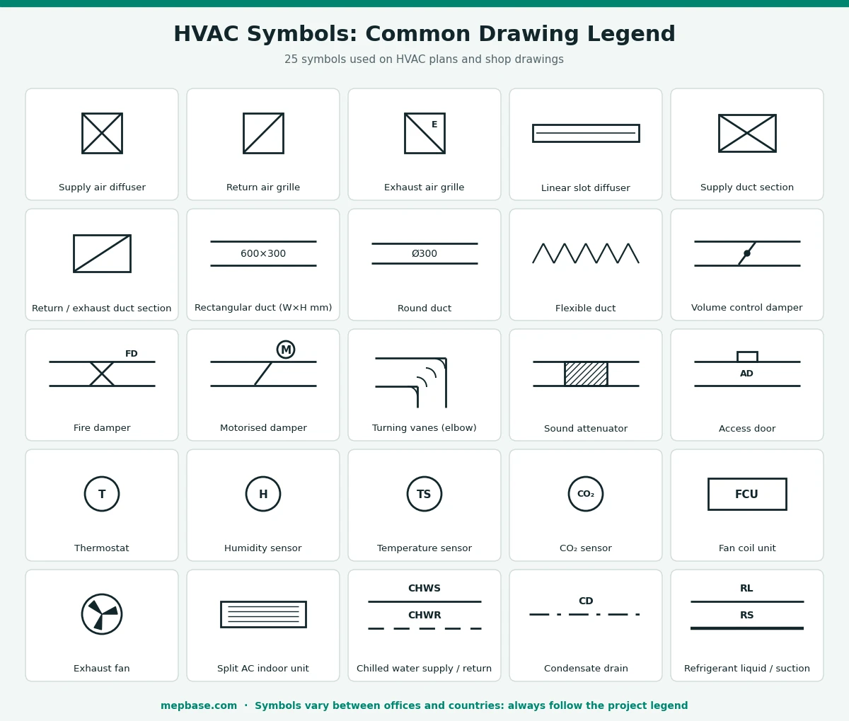
HVAC drawings use a shorthand of symbols and abbreviations for diffusers, ducts, dampers, sensors and pipes. This chart shows the HVAC symbols you will meet most often on plans and shop drawings, with their abbreviations and what they mean, plus free DWG blocks to use in your own drawings.
Quick answer
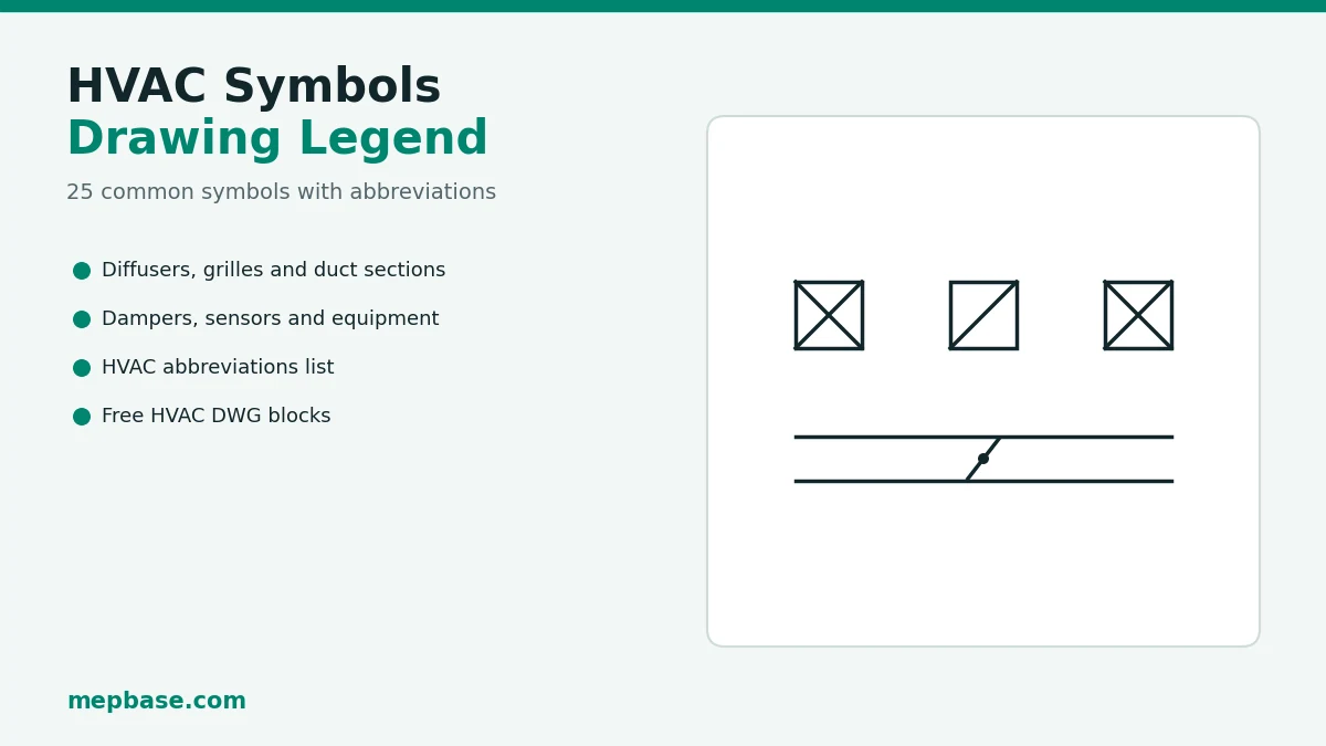
A square with an X is a supply diffuser, a square with one diagonal is a return or exhaust grille, a line across a duct with a pivot dot is a volume damper, and a circle with T is a thermostat. Every project has its own legend, so always check it first.
HVAC Symbols and Their Meaning
| Symbol | What it shows |
|---|---|
| Square with X | Supply air diffuser (ceiling) |
| Square with one diagonal | Return or exhaust air grille |
| Long narrow rectangle | Linear slot diffuser |
| Rectangle with X (in section) | Supply duct cut in section or turning up |
| Rectangle with one diagonal | Return or exhaust duct in section |
| Two parallel lines with size | Rectangular duct, width × height (e.g. 600×300) |
| Zig-zag line | Flexible duct |
| Line across duct with dot | Volume control damper (VCD) |
| Crossed lines + FD | Fire damper |
| Damper + M | Motorised damper |
| Curved blades in elbow | Turning vanes |
| Hatched block in duct | Sound attenuator |
| Circle with T / H / TS | Thermostat, humidity sensor, temperature sensor |
| Box with FCU | Fan coil unit |
| Circle with blades | Fan (exhaust, supply, jet) |
| Solid / dashed lines with CHWS, CHWR | Chilled water supply and return pipes |
HVAC Abbreviations
| Abbreviation | Meaning |
|---|---|
| AHU | Air handling unit |
| FCU | Fan coil unit |
| VAV / CAV | Variable / constant air volume box |
| SA / RA / EA / FA | Supply, return, exhaust, fresh (outdoor) air |
| CHWS / CHWR | Chilled water supply / return |
| HWS / HWR | Heating hot water supply / return |
| CD | Condensate drain |
| RL / RS | Refrigerant liquid / suction line |
| VCD | Volume control damper |
| FD / SD / FSD | Fire damper / smoke damper / fire and smoke damper |
| EF / KEF | Exhaust fan / kitchen exhaust fan |
| CU / DX | Condensing unit / direct expansion |
| BMS | Building management system |
How to Read HVAC Drawings
Each consultant has its own symbol set; the legend sheet overrides any general chart.
Trace supply from the AHU or FCU through ducts to diffusers, then return and exhaust back.
Duct sizes (W×H or Ø), airflow at each diffuser, and bottom-of-duct levels for coordination.
Dampers, access doors, sensors and attenuators are easy to miss but must be installed and accessible.
Size the ducts too
Convert airflow to duct size with velocity and friction checks.
Download HVAC Symbols (DWG)
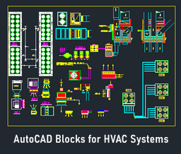
All 25 symbols from the chart as AutoCAD blocks (MB_HVAC_…), drawn at paper size in mm: scale them by your drawing scale, for example ×100 at 1:100.
Checking…
Frequently Asked Questions
What does a square with an X mean on an HVAC drawing?
Usually a supply air diffuser in plan, or a supply duct cut in section. The project legend confirms which.
What is the symbol for a fire damper?
Commonly a duct with crossed lines and the letters FD; smoke dampers use SD and combination units FSD.
What do CHWS and CHWR mean?
Chilled water supply and chilled water return, the pipes between the chiller and the cooling coils.
Are HVAC symbols standardised?
Partly. ASHRAE and ISO publish symbol sets, but most consultants use their own legend, so always read the legend sheet.
Related Downloads and Tools
- AutoCAD blocks for HVAC systems (DWG)
- Dynamic blocks for HVAC
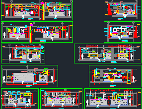
- HVAC shop drawing DWG
- HVAC installation details
- Plumbing symbols chart