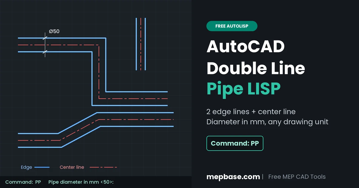
Drawing a pipe as two edge lines and a center line by hand means three offsets, two layer changes and a linetype fix for every run. This free AutoCAD double line pipe LISP does all of it while you route. Type PP, set the diameter once, and click the route. The pipe appears as three lines after every click.
It is made for MEP draftsmen who prepare plumbing, chilled water and fire fighting shop drawings, where pipes must be shown at true width with a center line for dimensions and coordination.
File Information
- File Name: Pipe3Line.lsp (inside Pipe3Line.zip)
- File Type: .lsp (AutoLISP)
- Command:
PP(full namePIPE3) - File Size: about 8 KB
- Software: Full AutoCAD on Windows, including AutoCAD MEP
- Usage: Free
What the Double Line Pipe LISP Does
- Draws three lines in one go: two edge lines at the pipe width and one center line between them.
- Takes the diameter in mm: type 50 for a 50 mm pipe. The LISP converts it to your drawing unit (mm, cm, meter, inch or feet) on its own.
- Updates live: the pipe is rebuilt after every point you pick, so you see the real width while routing.
- Remembers the size: the last diameter stays until you change it with the D option.
- Puts the center line on its own layer: CENTER linetype, with the dash length matched to the pipe size.
- Undo while routing: type U to remove the last point. After the command, one U removes the whole pipe.
How to Use the PP Command
- Type
APPLOAD, select Pipe3Line.lsp and click Load. Add it to the Startup Suite to load it in every drawing. - Make the pipe layer current, for example your chilled water or drainage layer.
- Type
PPand press Enter. - Type
D, press Enter, type the diameter in mm (for example50) and press Enter. Skip this step if the size shown is already correct. - Pick the start point, then the next points. Ortho, polar tracking and object snaps work as usual.
- Press Enter to finish. Press Enter again to repeat the command for the next pipe.
Layers and Linetypes
| Line | Layer | Linetype |
|---|---|---|
| Two edge lines | Current layer | ByLayer |
| Center line | Current layer name + -CL (same color) | CENTER |
| Center line, when the current layer is 0 | PIPE-CL | CENTER |
The -CL layer is created the first time it is needed. Freeze it when you plot a coordination layout that should show pipe edges only.
Which Diameter to Enter: Nominal Size or OD?
The LISP draws exactly the width you type. For a schematic layout the nominal size is enough. For a shop drawing, type the outside diameter, because clearances between pipes, walls and cable trays are checked edge to edge.
| Nominal Size | Steel Pipe OD (mm) | Type in PP |
|---|---|---|
| DN25 (1″) | 33.4 | 33.4 |
| DN50 (2″) | 60.3 | 60.3 |
| DN80 (3″) | 88.9 | 88.9 |
| DN100 (4″) | 114.3 | 114.3 |
| DN150 (6″) | 168.3 | 168.3 |
| DN200 (8″) | 219.1 | 219.1 |
Steel pipe outside diameters are as per ASME B36.10 (2022 edition). PVC, copper and HDPE pipes have different outside diameters, so check the manufacturer’s data. For all sizes and schedules, see our pipe size chart.
Insulated pipes: for chilled water, add twice the insulation thickness to the OD. A DN100 pipe with 50 mm insulation is drawn as 114.3 + 100 = 214.3 mm. The insulation thickness here is an example only. Use the value from your project specification.
Practical Notes
| Problem | Cause | Fix |
|---|---|---|
| Pipe is far too big or too small | The drawing unit setting does not match how the drawing was made | Type UNITS and set Insertion scale to the real drawing unit |
| Only one line is visible | The view is zoomed in closer than the pipe width, so the edges are off screen | The LISP zooms to the pipe automatically. If needed, use Zoom Extents |
| Edge lines missing after a bend | A segment is shorter than the pipe width | Type U and pick the point further away |
| Center line looks continuous | CENTER linetype could not be loaded, or the view needs a regen | Type REGEN. If it stays solid, load CENTER from the LINETYPE command |
| Bends are sharp corners | The LISP draws the pipe run only, not fittings | Place elbows and tees from a fittings block library |
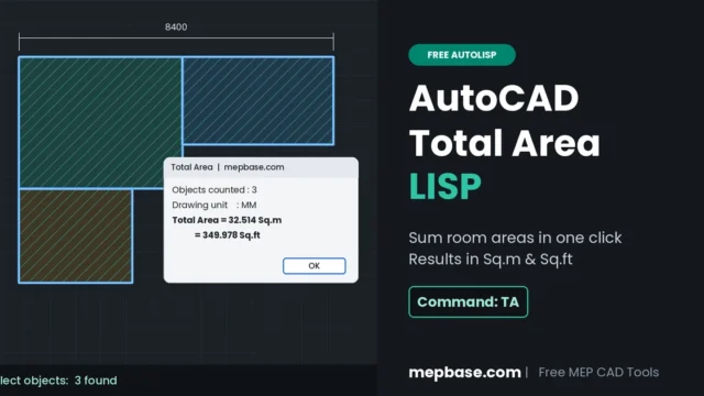
For elbows, tees and reducers at true size, use our AutoCAD MEP fittings blocks. To check floor areas for the same layout, see the AutoCAD Total Area LISP.
Tip: an .lsp file is plain text. You can open it in Notepad to review the code before loading it.
Download Double Line Pipe LISP
Click below to download Pipe3Line.zip. The link will appear after a short wait.
Checking…
Related Downloads
- AutoCAD Total Area LISP (TA Command)
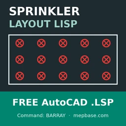
- Fire Sprinkler Layout LISP for AutoCAD
- Pipe Fitting CAD Blocks
- Pipe Size Chart: NPS, OD and Schedule 40/80
- All AutoLISP Tools
Frequently Asked Questions
Is the AutoCAD double line pipe LISP free?
Yes. Pipe3Line.lsp is free to download and use in your projects.
Do I enter the diameter in mm or in drawing units?
Always in mm. The LISP reads the drawing unit from the Insertion scale setting and converts the size. In a drawing made in meters, typing 50 gives a pipe 0.05 units wide.
Which AutoCAD versions does it work in?
It works in full AutoCAD on Windows, including AutoCAD MEP. It may not run in AutoCAD LT, because it uses Visual LISP (vla-) functions.
Does it draw elbows at the bends?
No. Bends are drawn as sharp corners. Add elbow and tee blocks where the drawing needs them.
Can I change the center line color or linetype?
Yes. The center line uses ByLayer properties, so change the -CL layer in the Layer Properties Manager and every center line on it follows.
How do I draw the next pipe with the same size?
Press Enter to repeat PP and pick the start point. The last diameter is kept until you change it with the D option.
Found a bug or want a new feature, like pipe size labels or elbows at bends? Leave a comment below. Stay connected with MEPBase.com for more AutoLISP tools, DWG files and AutoCAD add-ons.