Duct Sizing Explained: Equal Friction vs Velocity Method (Step-by-Step + Example)
Sizing ductwork correctly is one of the most important skills in HVAC design. Get it wrong and you end up with noisy systems, high fan energy, unbalanced airflow, and unhappy occupants. Get it right and the system is quiet, efficient, and easy to balance.
In this guide we’ll break down the two most widely used manual duct sizing methods — the equal friction method and the velocity reduction method — with clear steps, the formulas you actually need, and a fully worked example. If you’d rather skip the chart-reading, you can size any section in seconds with the free MEPBase Duct Size Calculator.
The One Formula Behind All Duct Sizing
Every method starts from the same continuity equation:
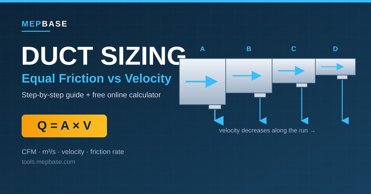
Q = A × V
Where:
- Q = airflow (m³/s or CFM)
- A = duct cross-sectional area (m² or ft²)
- V = air velocity (m/s or fpm)
Rearranged to find the area you need:
A = Q / V
For a round duct, the diameter is:
D = √(4A / π) = 1.128 × √A
That’s it. The “method” you choose simply decides how you pick the velocity (or the friction rate) for each section of the system. Everything else follows from the formula above.
Unit tip: Keep units consistent. In SI, use Q in m³/s, A in m², V in m/s. To convert: 1 L/s = 0.001 m³/s, 1 m/s ≈ 196.85 fpm, 1 L/s ≈ 2.119 CFM.
Our Example System
We’ll use the same simple supply system for both methods so you can compare results directly.
A fan feeds a trunk duct serving four ceiling diffusers, each delivering 250 L/s (≈ 530 CFM). Because each diffuser draws air off the trunk, the flow drops section by section:
| Section | Serves | Airflow (L/s) | Airflow (CFM) |
|---|---|---|---|
| A (main) | Fan → Diffuser 1 | 1000 | 2119 |
| B | Diffuser 1 → 2 | 750 | 1589 |
| C | Diffuser 2 → 3 | 500 | 1059 |
| D | Diffuser 3 → 4 | 250 | 530 |
Method 1: Equal Friction Method
This is the most popular method for low-velocity supply and return systems. The idea is simple: you keep the friction loss per unit length constant across the whole system, then read off the diameter for each section’s airflow.
Steps
- Calculate the total airflow the system must deliver (sum of all outlets).
- Select a friction rate. A typical design value is 0.8–1.0 Pa/m (about 0.08–0.10 in. wg per 100 ft). Lower = bigger, quieter, more expensive ducts.
- For each section, take its airflow and read the duct diameter that produces your chosen friction rate — from a friction chart, a ductulator, or the online calculator.
- Note the resulting velocity. With equal friction, velocity naturally decreases toward the ends of the run — which makes the system semi-self-balancing.
- Select the nearest standard duct size and re-check the velocity against noise limits.
Worked Example (friction rate ≈ 1.0 Pa/m)
| Section | Airflow (L/s) | Diameter (mm)* | Velocity (m/s)* |
|---|---|---|---|
| A | 1000 | ~450 | ~6.3 |
| B | 750 | ~400 | ~5.6 |
| C | 500 | ~355 | ~5.0 |
| D | 250 | ~280 | ~4.0 |
*Approximate values read at a constant ~1.0 Pa/m. Confirm exact figures with a friction chart or the MEPBase Duct Size Calculator.
Notice how the velocity drops automatically from 6.3 m/s at the main to about 4.0 m/s at the last branch — even though we never picked a velocity. That self-reducing behaviour is the main advantage of equal friction.
Pros and Cons
Pros: Fast, consistent, and reasonably self-balancing for symmetrical layouts. Industry standard for most commercial supply/return air.
Cons: Doesn’t account for static pressure regain, so very long runs may still need balancing dampers. On highly asymmetric systems, the index (longest) run can become the bottleneck.
Method 2: Velocity Reduction Method
Here, instead of fixing the friction rate, you assign a target velocity to each section — highest at the main, reducing step-by-step toward the outlets. Then you size each duct directly from A = Q / V.
Steps
- Choose a velocity for the main duct based on the application and noise limits (see the table below).
- Reduce the velocity progressively for each downstream section.
- Calculate the area for each section: A = Q / V.
- Find the diameter: D = 1.128 × √A.
- Round to the nearest standard size and recompute the actual velocity.
Worked Example
Target velocities (decreasing toward the ends): A = 6.0, B = 5.5, C = 5.0, D = 4.0 m/s.
| Section | Q (L/s) | Target V (m/s) | A = Q/V (m²) | Calc. Ø (mm) | Selected Ø (mm) | Actual V (m/s) |
|---|---|---|---|---|---|---|
| A | 1000 | 6.0 | 0.1667 | 461 | 450 | 6.3 |
| B | 750 | 5.5 | 0.1364 | 417 | 400 | 6.0 |
| C | 500 | 5.0 | 0.1000 | 357 | 355 | 5.1 |
| D | 250 | 4.0 | 0.0625 | 282 | 280 | 4.1 |
Sample calculation for Section A:
A = 1.0 / 6.0 = 0.1667 m² → D = 1.128 × √0.1667 = 0.461 m = 461 mm → select 450 mm, actual velocity = 1.0 / (π × 0.45² / 4) = 6.3 m/s.
When you round down to the nearest standard size, velocity rises slightly; round up and it falls. To stay quiet, many designers round up to the next standard size.
Pros and Cons
Pros: Quick and intuitive for small or simple systems; gives the designer direct control over velocity (and therefore noise) in each section.
Cons: Relies heavily on the designer’s experience to pick good velocities. Results are less consistent than equal friction and can produce unbalanced systems that need more dampers.
Equal Friction vs Velocity Method: Which Should You Use?
| Factor | Equal Friction | Velocity Reduction |
|---|---|---|
| Best for | Most low-velocity supply/return systems | Small or simple layouts |
| What’s fixed | Friction rate (Pa/m) | Velocity per section |
| Balancing | Semi-self-balancing | Often needs more dampers |
| Skill required | Low–medium | Medium (judgement on velocities) |
| Popularity | Industry default | Common for quick design |
For larger or high-velocity systems, engineers sometimes use the more advanced static regain method, which recovers velocity pressure to keep static pressure nearly constant — but for everyday low-velocity work, equal friction is the go-to, with velocity reduction as a fast alternative.
Recommended Maximum Velocities (Low-Velocity Systems)
Use these as a starting guide for noise control, and always defer to ASHRAE/SMACNA guidance and local codes.
| Application | Main Duct (m/s) | Branch Duct (m/s) |
|---|---|---|
| Residences | 3.5 – 4.5 | 3.0 – 3.5 |
| Offices, hotels, apartments | 5.0 – 6.5 | 3.5 – 5.0 |
| Industrial / commercial | 6.0 – 9.0 | 4.0 – 6.5 |
Lower velocities = quieter systems but larger, costlier ducts. Higher velocities save space and material but increase noise and fan energy.
Converting Round to Rectangular Ducts
Round ducts are most efficient, but space often forces rectangular ones. To find the rectangular duct that carries the same airflow at the same friction loss, use the equivalent diameter equation:
D_eq = 1.30 × (a × b)^0.625 / (a + b)^0.250
Where a and b are the rectangular duct sides. Pick a height to suit your ceiling space, then solve for the width that matches your required equivalent diameter. The duct calculator handles this conversion automatically.
Common Duct Sizing Mistakes to Avoid
- Sizing on peak velocity alone and ignoring the cumulative pressure drop along the index run.
- Forgetting fittings. Elbows, transitions, and dampers add significant equivalent length — always include them in your total pressure drop.
- Over-reducing branches, which starves the diffusers furthest from the fan.
- Mixing units (CFM with m²) — a classic source of errors.
- Skipping the noise check after rounding to standard sizes.
Frequently Asked Questions
What friction rate should I use for duct sizing?
For most low-velocity commercial systems, 0.8–1.0 Pa/m (≈ 0.08–0.10 in. wg per 100 ft) is a good default. Use lower values where quietness matters more than cost.
Which duct sizing method is most accurate?
For long or high-velocity systems, the static regain method is the most precise. For typical projects, equal friction gives reliable, well-balanced results and is the industry standard.
Can I size ducts without a friction chart?
Yes. An online tool like the MEPBase Duct Size Calculator lets you enter airflow and either friction rate or velocity, and instantly returns the duct size and velocity — round or rectangular.
Why does velocity drop along an equal-friction duct run?
Because the friction rate is held constant while the airflow decreases at each branch. Smaller flow needs a smaller diameter, and the net effect is a steadily falling velocity toward the outlets.
Key Takeaways
- All duct sizing comes back to Q = A × V.
- Equal friction keeps the friction rate constant and is the most common, semi-self-balancing method.
- Velocity reduction sets a target velocity per section — fast and intuitive, but more dependent on judgement.
- Always select standard duct sizes, re-check velocities for noise, and account for fittings.
Ready to size your system? Try the free MEPBase Duct Size Calculator — enter your airflow, choose equal friction or velocity, and get the duct size, velocity, and pressure drop instantly.