Standpipe System Design to NFPA 14: Classes, Flow, Pressure and PRVs Step by Step
In a high-rise fire, firefighters do not carry hose up from the street. They connect to the standpipe on the fire floor and expect water at the right pressure, every time. This guide walks through standpipe system design step by step to NFPA 14: choosing the class and type, locating hose connections, flow and pressure requirements, pipe sizing, pressure limits and pressure-reducing valves, with a worked example for a 12-storey building.
What a standpipe system is
A standpipe system is a network of vertical risers and horizontal pipes with hose connections on each floor, supplied by a fire pump, a tank, the city main or a fire department connection. It lets firefighters, or trained occupants, attack a fire with hose streams without laying hose from outside. In fully sprinklered buildings the standpipes are often combined with the sprinkler risers.
Step 1: Choose the standpipe class
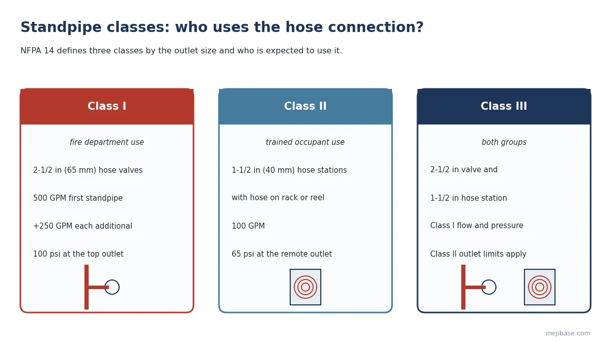
| Class | Hose connection | Intended user | Flow | Residual pressure |
|---|---|---|---|---|
| Class I | 2-1/2 in (65 mm) hose valve | Fire department | 500 GPM first standpipe + 250 GPM each additional | 100 psi (6.9 bar) at the most remote outlet |
| Class II | 1-1/2 in (40 mm) hose station | Trained occupants | 100 GPM | 65 psi (4.5 bar) at the most remote outlet |
| Class III | Both 2-1/2 in and 1-1/2 in | Both | As Class I | As Class I |
Most modern high-rise buildings use Class I, because occupant hose stations are rarely used safely and many codes no longer require them in sprinklered buildings. Check the building code and the local fire authority.
Step 2: Choose the system type
- Automatic wet: pipes full of water, with a water supply that can meet the demand automatically. The usual choice for heated high-rise buildings.
- Automatic dry: pipes filled with pressurized air, with a dry pipe valve that admits water when a hose valve opens. Used where pipes could freeze.
- Semiautomatic dry: dry pipes with a deluge-type valve opened by a remote control device at each hose connection.
- Manual dry: no permanent water supply; water comes only from the fire department pumper through the fire department connection. Common in open parking structures.
- Manual wet: pipes kept full by a small supply for leak detection, but the fire flow comes from the fire department.
High-rise buildings generally need an automatic or semiautomatic system, because fire department pumpers alone cannot reliably deliver the required pressure to the upper floors.
Step 3: Locate the hose connections
- Exit stairs: a Class I hose connection in every required exit stair, at each floor level landing (main or intermediate landing as accepted by the authority).
- Roof: a hose connection at the top of the stair or on the roof where the roof is accessible and not steeply sloped.
- Horizontal exits: a connection on each side of a wall opening used as a horizontal exit.
- Travel distance: where any part of a floor is more than 150 ft (46 m) of travel from a hose connection in an unsprinklered building, or 200 ft (61 m) in a sprinklered building, add more connections.
- Class II: place hose stations so every part of the floor is within 130 ft (40 m) of a station, based on 100 ft of hose plus a 30 ft stream.
Step 4: Set flow and pressure
For Class I and III systems, the most remote standpipe flows 500 GPM (1,893 L/min) and each additional standpipe adds 250 GPM (946 L/min), up to 1,000 GPM in fully sprinklered buildings and 1,250 GPM otherwise. The hydraulically most remote 2-1/2 in outlet must have at least 100 psi (6.9 bar) residual at its flow.
In a combined system in a fully sprinklered building, the sprinkler demand generally does not have to be added to the standpipe demand when the standpipe demand is the larger. Check flows with the Standpipe Calculator.
Step 5: Size the pipes
NFPA 14 sets minimum standpipe sizes: 4 in (100 mm) for Class I and III standpipes, and 6 in (150 mm) for standpipes that are part of a combined sprinkler and standpipe system. Smaller sizes are only permitted where a hydraulic calculation shows the demand can be met. Size horizontal mains and the common supply for the total flow of all standpipes.
The pressure needed at the pump discharge is:
Pump discharge pressure = 100 psi + Elevation (0.433 psi/ft) + Friction losses
Use the Fire Hydraulic Calculator for friction losses, and see Fire Pump Sizing to NFPA 20 to select the pump.
Step 6: Check maximum pressures and fit pressure-reducing valves
Pressure that is high enough at the top of a tall building is too high at the bottom. NFPA 14 limits it:
- Where static pressure at a 2-1/2 in hose connection exceeds 175 psi (12.1 bar), a pressure-regulating device is required to limit static and residual pressure at the outlet to 175 psi.
- Where residual pressure at a 1-1/2 in hose connection exceeds 100 psi (6.9 bar), a pressure-regulating device is required.
- Maximum pressure at any point in a system zone is limited to 350 psi (24.1 bar). Taller buildings are split into vertical zones, each with its own pump or pressure-reducing stations.
Check static pressure with the pump at churn, because that is the highest pressure the outlets will see.
Standpipe system design: worked example for a 12-storey building
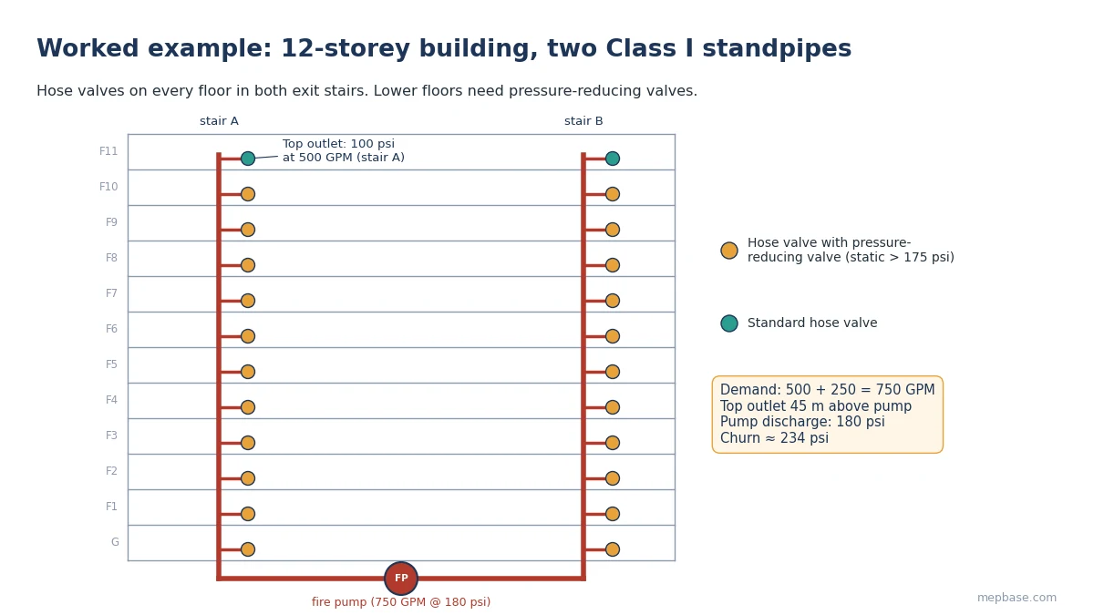
A fully sprinklered 12-storey office building (ground plus 11 floors) has two exit stairs and a combined automatic wet Class I system. Floor-to-floor height is 4 m, and hose valves sit 1.2 m above each floor. The topmost outlet is 45.2 m (148 ft) above the fire pump. The hydraulic calculation gives 16 psi friction loss at design flow.
| Step | Calculation | Result |
|---|---|---|
| Class and type | fire department use, heated building | Class I, automatic wet |
| Flow demand | 500 + 250 | 750 GPM (47.3 L/s) |
| Elevation to top outlet | 148 × 0.433 | 64 psi |
| Pump discharge pressure | 100 + 64 + 16 | 180 psi (12.4 bar) |
| Fire pump | 750 GPM at 180 psi | |
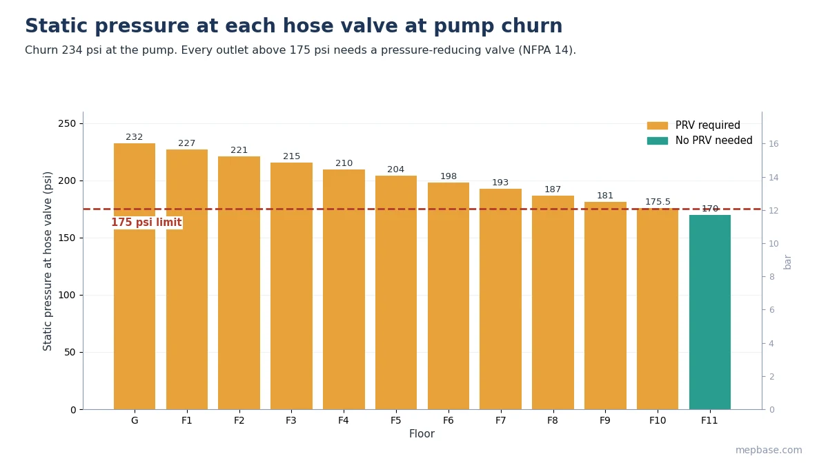
| Churn pressure (130%) | 1.3 × 180 | 234 psi |
| Static at F10 outlet (41.2 m) | 234 − 135 × 0.433 | 175.5 psi: PRV required |
| Static at F11 outlet (45.2 m) | 234 − 148 × 0.433 | 170 psi: no PRV needed |
| PRVs | G to F10, two stairs | 22 pressure-reducing hose valves |
| Standpipe size | combined system | 6 in (150 mm) |
Because churn plus suction pressure exceeds 175 psi, the pump room and lower risers also need components rated for the higher pressure (commonly 300 psi). The water supply for this system is sized in Fire Water Tank Sizing.
Fire department connection
Every standpipe system zone needs a fire department connection (FDC), so the fire service can pump into the system. Locate it on the street side of the building where it is visible and accessible, with a clear sign showing which system and floors it serves, and fit a check valve so water cannot flow out through it.
Common mistakes
- Sizing the pump for the top outlet and forgetting that lower outlets then exceed 175 psi.
- Checking outlet pressure at rated flow instead of at churn.
- Using 4 in standpipes in a combined system without a hydraulic calculation to justify them.
- Missing hose connections where travel distance on large floors exceeds 150 ft or 200 ft.
- Leaving out the roof outlet or the connections at horizontal exits.
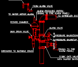
For standard installation details, see Fire Fighting CAD Details and Fire Fighting System Design Calculation.
Frequently asked questions
What is the minimum pressure for a Class I standpipe?
100 psi (6.9 bar) residual at the outlet of the hydraulically most remote 2-1/2 in hose connection, at the design flow (NFPA 14).
What is the flow rate for a standpipe system?
500 GPM for the most remote standpipe plus 250 GPM for each additional standpipe, up to 1,000 GPM in fully sprinklered buildings and 1,250 GPM otherwise.
When are pressure-reducing valves required on standpipes?
When static pressure at a 2-1/2 in hose connection exceeds 175 psi, or residual pressure at a 1-1/2 in hose connection exceeds 100 psi.
What size should a standpipe be?
At least 4 in (100 mm) for Class I and III, and 6 in (150 mm) for combined sprinkler and standpipe systems, unless a hydraulic calculation justifies a smaller size.