Fire Pump Sizing to NFPA 20: Flow, Pressure, Driver and Jockey Pump Step by Step
A fire pump that is a little too small fails the acceptance test; one that is far too big can push churn pressure past what the pipes and valves are rated for. This guide walks through fire pump sizing step by step to NFPA 20: system flow demand, required discharge pressure, suction pressure, rated capacity, curve checks, driver size, pressure ratings and jockey pump settings, with a full worked example for a high-rise standpipe system.
What fire pump sizing involves
A fire pump boosts the water supply so the most demanding fire protection system it serves (sprinklers, standpipes or both) gets its required flow and pressure. Sizing means choosing a rated flow and rated pressure, then checking the whole pump curve, the driver, the system pressure ratings and the pressure maintenance (jockey) pump.
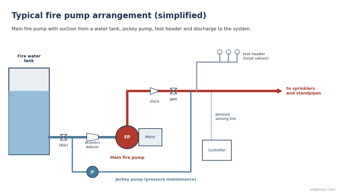
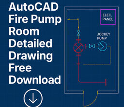
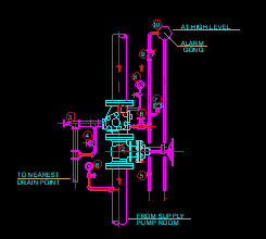
For pump room layouts and details, see the Fire Pump Room DWG and the AutoCAD Fire Pump Room Detailed Drawing.
Step 1: Determine the system flow demand
The pump’s rated flow comes from the largest demand among the systems it supplies:
- Sprinkler systems: the hydraulically calculated demand of the most remote design area (NFPA 13), plus the hose stream allowance where the pump supplies hose connections or hydrants. See Fire Fighting System Design Calculation for the sprinkler side.
- Class I and III standpipes: 500 GPM (1,893 L/min) for the first standpipe plus 250 GPM (946 L/min) for each additional standpipe, up to 1,000 GPM in fully sprinklered buildings and 1,250 GPM otherwise (NFPA 14). Use the Standpipe Calculator to check this.
- Combined systems: in a fully sprinklered building, the sprinkler demand generally does not need to be added to the standpipe demand when the standpipe demand is the larger of the two. Confirm with NFPA 14 and the local authority.
Step 2: Calculate the pressure needed at the pump discharge
Discharge pressure = Residual pressure at the remote outlet + Elevation + Friction losses
- Residual pressure: 100 psi (6.9 bar) at the topmost 2-1/2 in hose connection for Class I and III standpipes, or the sprinkler system’s calculated demand at its base.
- Elevation: 0.433 psi per foot of height (9.81 kPa per metre) from the pump to the remote outlet.
- Friction losses: from the hydraulic calculation of the riser, mains, valves and fittings at design flow.
Step 3: Subtract the available suction pressure
Net pump pressure = Discharge pressure − Suction pressure
With a water tank and flooded suction, suction pressure is the static head from the minimum water level to the pump, minus suction pipe friction. With a city supply, it is the residual pressure available at the design flow, taken from a hydrant flow test; see the Hydrant Flow Test Calculator. Always size on the worst case (lowest tank level or lowest city residual).
Step 4: Select the rated capacity and check the pump curve
Fire pumps come in standard rated capacities: 25, 50, 100, 150, 200, 250, 300, 400, 450, 500, 750, 1,000, 1,250, 1,500, 2,000, 2,500 and 3,000 GPM, and larger. Select a rated flow and pressure that cover the demand, then check the full curve against NFPA 20:
- Churn (shutoff): pressure must not exceed 140% of rated pressure.
- 150% of rated flow: pressure must be at least 65% of rated pressure.
- The system demand can fall anywhere up to 150% of rated flow, as long as the curve delivers the required pressure at that flow.
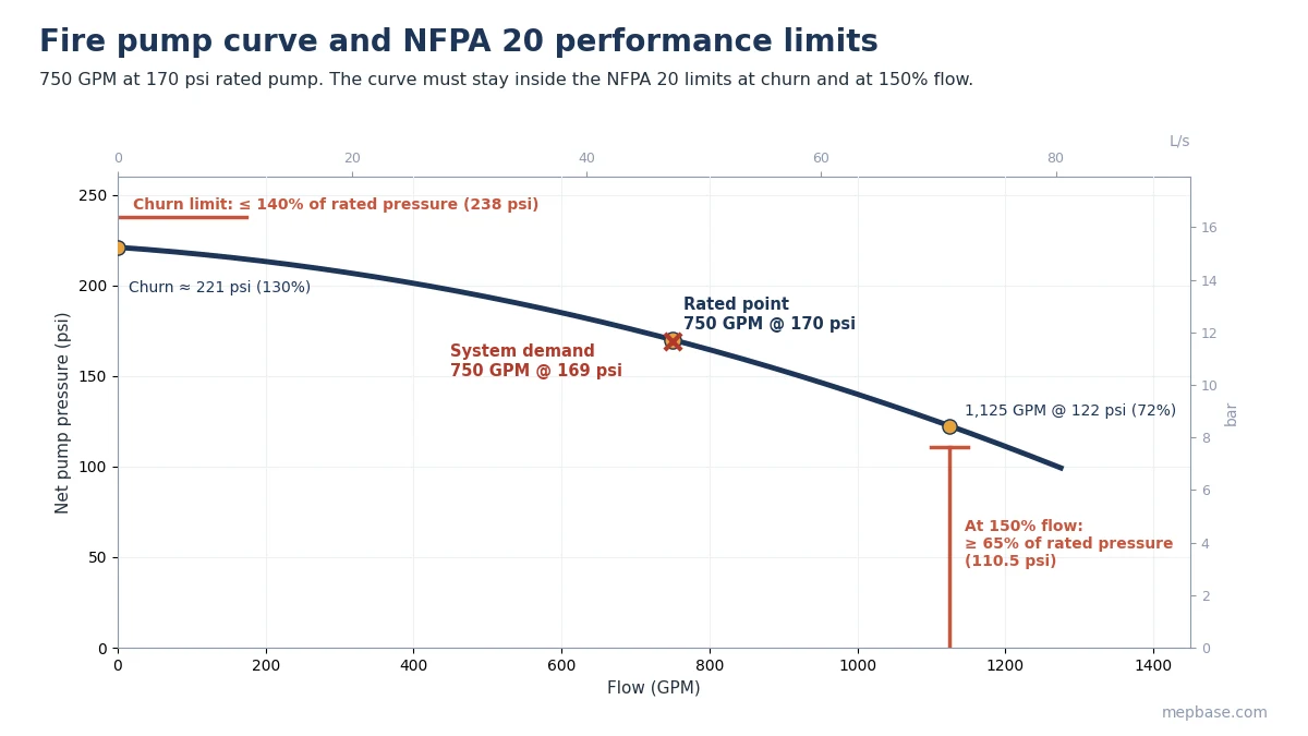
Picking a pump much larger than needed is not “safe”. It raises churn pressure, which can push the system over its component ratings (Step 6).
Step 5: Size the driver
BHP = GPM × psi / (1,714 × Pump efficiency)
kW = L/s × kPa / (1,000 × Pump efficiency)
Check the manufacturer’s curve for the maximum power anywhere from churn to 150% of rated flow. For an electric motor, that maximum must not exceed the motor’s rated power times its service factor (1.15 for most NEMA motors). Diesel engines are rated at site conditions, so derate for altitude above 300 ft (91 m) and for ambient temperatures above 77°F (25°C) as NFPA 20 requires. You can estimate power with the Pump Horsepower Calculator.
Step 6: Check system pressure ratings
Maximum system pressure = Churn pressure + Maximum static suction pressure
Most standard fire protection components are rated for 175 psi (12.1 bar). If the maximum pressure is higher, use components with a higher rating (commonly 300 psi / 20.7 bar) in the pump room and lower floors, and fit pressure-regulating devices at hose connections where NFPA 14 requires them. Do not rely on a relief valve to fix an oversized pump; NFPA 20 only accepts relief valves in specific cases such as diesel drivers and variable speed pumps.
Step 7: Size the jockey pump and set the pressures
A jockey pump keeps the system pressurized and makes up small leaks so the main pump does not start unnecessarily. It is typically sized to replace allowable leakage within about 10 minutes, and its flow must be less than the flow of one sprinkler, so a real sprinkler activation always starts the main pump.
The NFPA 20 annex suggests these settings:
- Jockey pump stop = main pump churn pressure + minimum static suction pressure
- Jockey pump start = jockey stop − 10 psi
- Main fire pump start = jockey start − 5 psi
- Each additional (standby) pump start = 10 psi below the previous pump
Fire pump sizing: worked example for a high-rise standpipe system
A fully sprinklered office building has two Class I standpipes with a combined sprinkler and standpipe system. The topmost hose connection is 120 ft (36.6 m) above the fire pump. Water comes from a ground-level tank; minimum water level gives 2 psi static suction and a full tank gives 6 psi. The hydraulic calculation gives 18 psi friction loss at design flow, and suction pipe friction is 1 psi.
| Step | Calculation | Result |
|---|---|---|
| Standpipe flow demand | 500 + 250 | 750 GPM (47.3 L/s) |
| Residual at top outlet | NFPA 14, Class I | 100 psi |
| Elevation | 120 × 0.433 | 52 psi |
| Friction losses | hydraulic calculation | 18 psi |
| Discharge pressure | 100 + 52 + 18 | 170 psi (11.7 bar) |
| Net suction | 2 − 1 | 1 psi |
| Net pump pressure | 170 − 1 | 169 psi |
| Pump selected | standard rating | 750 GPM at 170 psi |
| Churn check | 221 psi ≤ 1.40 × 170 = 238 psi | OK |
| 150% flow check | 1,125 GPM at 122 psi ≥ 0.65 × 170 = 110.5 psi | OK |
| Power at rated point | 750 × 170 / (1,714 × 0.70) | 106 BHP (79 kW) |
| Motor | max on curve ≈ 115 BHP ≤ 125 × 1.15 | 125 HP (93 kW) |
| Maximum system pressure | 221 + 6 | 227 psi: use 300 psi rated components |
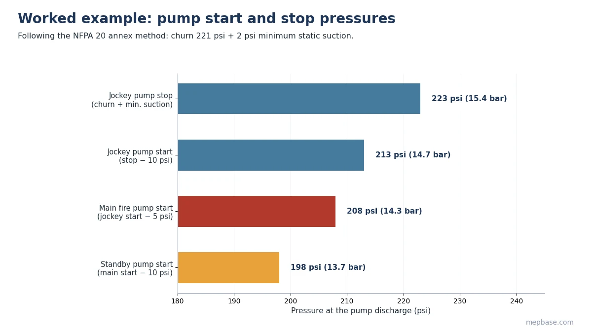
With churn at 221 psi and 2 psi minimum suction, the jockey pump stops at 223 psi and starts at 213 psi, and the main pump starts at 208 psi. A jockey pump of about 10 GPM suits a system of this size. Run your own numbers in the Fire Pump Selection Calculator, and size the water supply with the Fire Water Tank Calculator.
Common mistakes
- Sizing on sprinkler demand alone when the pump also feeds standpipes or hydrants.
- Using the full-tank water level instead of the minimum level for suction pressure.
- Selecting a much larger pump “for safety” and ending up with churn pressure above the component ratings.
- Sizing the electric motor at the rated point instead of the maximum power up to 150% flow.
- Setting the jockey pump start pressure below the main pump start, so the main pump runs for every small leak.
For valve, pump and fitting blocks for your pump room drawings, see Fire Fighting Valves, Pumps and Dynamic Fittings DWG Blocks.
Frequently asked questions
What are the NFPA 20 fire pump curve requirements?
Churn pressure must not exceed 140% of rated pressure, and at 150% of rated flow the pump must deliver at least 65% of rated pressure.
How do you calculate fire pump pressure?
Add the residual pressure needed at the remote outlet, the elevation (0.433 psi per foot) and the friction losses, then subtract the available suction pressure.
How is a jockey pump sized?
It is sized to make up allowable system leakage, usually within about 10 minutes, with a flow smaller than one sprinkler so that any real activation starts the main pump.
What is the standpipe flow demand for a fire pump?
For Class I and III systems, 500 GPM for the first standpipe and 250 GPM for each additional one, up to 1,000 GPM in fully sprinklered buildings (NFPA 14).