Irrigation Pump Room Sectional Plan DWG Free Download
If you are looking for a clean and practical irrigation pump room DWG, this drawing set is a strong reference. It presents a pump room sectional plan with clear mechanical works information, including equipment layout, piping routing, valve arrangement, levels, and installation notes. This type of CAD file is commonly used for irrigation and landscape water supply systems where pump selection, suction conditions, and maintenance access must be correctly coordinated.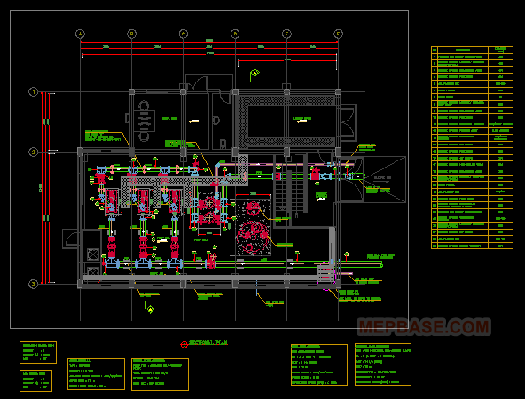
What’s Included in This Pump Room DWG?
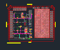
- Pump Room Sectional Plan: Structural section view with pump installation level, access, and clearance understanding.
- Mechanical Works Layout: Pump arrangement, discharge routing, and serviceability intent.
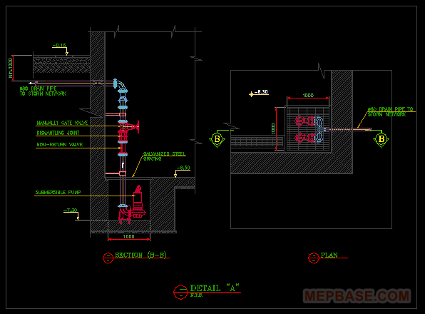
- Piping & Valve Arrangement: Isolation valves, check valves, reducers, bends, drain and air release provisions (as shown in the details).
- Notes / Legend / Schedule: Mechanical notes, tagging references and installation guidance for site teams.
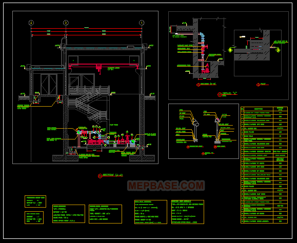
Sectional Plan Breakdown (How to Read the Drawing)
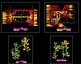
The sectional view is the most important part of this file. It shows the vertical relationship between the irrigation tank and the pump room, including the pump foundation and the routing of suction and discharge lines. This makes it easier to verify:
- Flooded suction condition (preferred for stable pump operation).
- Proper maintenance access around pumps and valves.
- Clear pipe routing through walls/slabs with logical penetration points.
- Drain provisions for leakage and maintenance water handling.
Mechanical Equipment & Installation Intent
The drawing indicates a professional mechanical approach for irrigation service:
- Pumps installed on a concrete base/foundation with clear connection zones.
- Suction piping arranged to minimize turbulence near the pump suction flange.
- Discharge piping routed with control and non-return protection.
- Valve placement positioned for operation and maintenance.
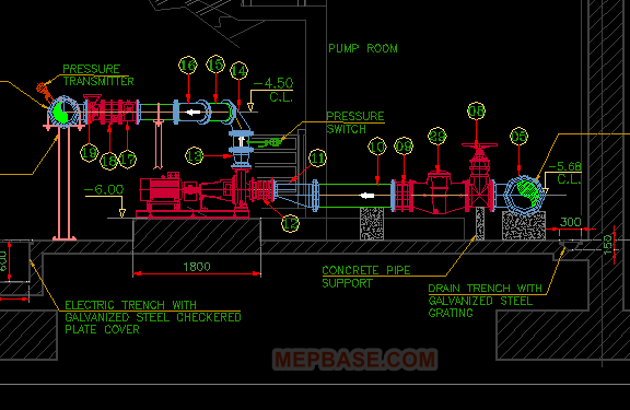
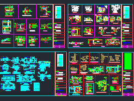
Piping, Valves & Fittings (Typical Components Shown)
This pump room mechanical drawing includes the core elements generally required for an irrigation pump station:
- Isolation valves (gate/butterfly type depending on specification).
- Check valves on discharge to prevent reverse flow and water hammer risk.
- Reducers and elbows oriented for proper flow control.
- Drain connection and basic service detailing for maintenance activities.
Irrigation Pump Calculations (Concept Used in This Type of Design)
Even when a DWG does not show the full numeric calc sheet, the design intent typically follows standard irrigation pump sizing logic:
1) Required Flow (Q)
Flow is based on irrigation demand (zones, sprinklers/drip requirement, operating schedule). A reliable irrigation pump piping layout aims to keep velocities within acceptable limits to reduce noise and friction losses.
2) Total Dynamic Head (TDH)
TDH generally includes:
- Static head (elevation difference from tank water level to the discharge point).
- Pipe friction loss (based on pipe length, diameter, and roughness).
- Fitting & valve losses (equivalent length / K-factor method).
- Safety margin for practical site variations.
3) Key Design Checks
- Confirm stable suction conditions (reduce cavitation risk).
- Verify valve accessibility and maintenance clearance.
- Ensure discharge arrangement provides backflow protection (check valve placement).
Why This DWG is Useful (MEP & Site Teams)
- Clear water pump room section detail for coordination.
- Good reference for irrigation pump installation drawing and site execution.
- Includes notes/legend that help standardize construction understanding.
- Ideal for converting into IFC/shop drawings with minimal rework.
Free Irrigation Pump Room DWG Download
Download the irrigation pump room DWG including sectional plan, piping layout, and mechanical notes. This AutoCAD drawing is provided for learning and project reference use.
Download the irrigation pump room DWG