
MEP Fittings and Valves Dynamic Blocks Library – Free AutoCAD DWG
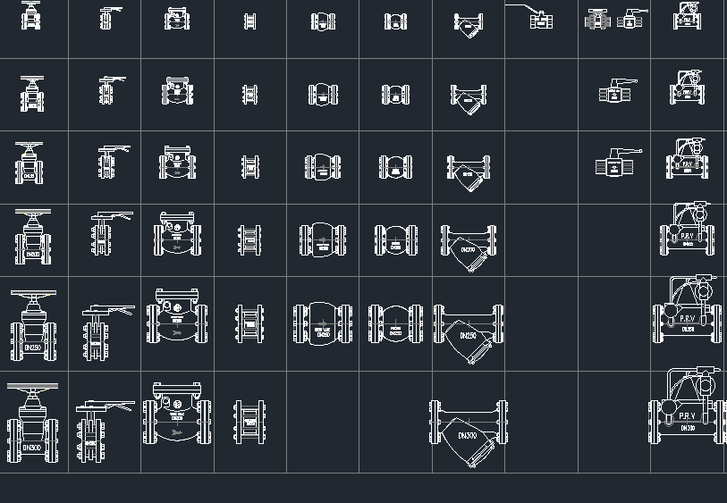
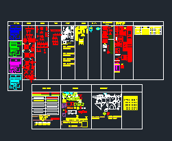
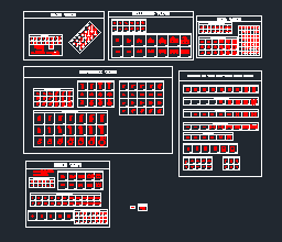
This free AutoCAD library brings together the piping fittings, valves and MEP symbols a draughtsman reaches for on almost every plumbing, fire fighting and HVAC drawing. Every item is a dynamic block with plan, side, front and top views built in as visibility states, and every block already carries an integrated wipeout, so it cleanly masks the pipe line behind it without any manual trimming.
The file covers welded black steel and stainless steel fittings, PPR fittings, uPVC fittings, a full valve and instrument set, AC condensate PVC fittings, and a set of electrical, low-voltage and mechanical symbol legends. Sizes run from DN15 up to DN800 for steel, so one file serves everything from a villa water supply layout to a fire pump room header.
What the Library Contains
1. Welded Black Steel and Stainless Steel Fittings
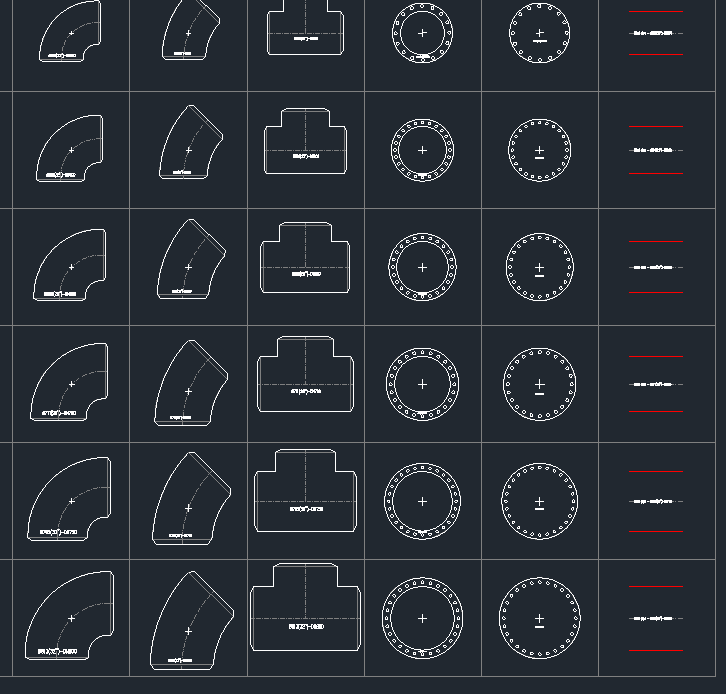
The steel set includes 90° elbow, 45° elbow, equal tee, flange, blind flange and black steel pipe, plus separate tables of reducers and reducing tees. This is the set to use for fire fighting mains, sprinkler risers, fire pump suction and discharge headers, and chilled water distribution.
| Item | Nominal OD | Inch Size | DN |
|---|---|---|---|
| 1 | ø21 | 1/2″ | DN15 |
| 2 | ø27 | 3/4″ | DN20 |
| 3 | ø34 | 1″ | DN25 |
| 4 | ø42 | 1-1/4″ | DN32 |
| 5 | ø49 | 1-1/2″ | DN40 |
| 6 | ø60 | 2″ | DN50 |
| 7 | ø73 | 2-1/2″ | DN65 |
| 8 | ø90 | 3″ | DN80 |
| 9 | ø114 | 4″ | DN100 |
| 10 | ø140 | 5″ | DN125 |
| 11 | ø168 | 6″ | DN150 |
| 12 | ø220 | 8″ | DN200 |
| 13 | ø273 | 10″ | DN250 |
| 14 | ø324 | 12″ | DN300 |
| 15 | ø355 | 14″ | DN350 |
| 16 | ø406 | 16″ | DN400 |
| 17 | ø457 | 18″ | DN450 |
| 18 | ø508 | 20″ | DN500 |
| 19 | ø559 | 22″ | DN550 |
| 20 | ø610 | 24″ | DN600 |
| 21 | ø660 | 26″ | DN650 |
| 22 | ø711 | 28″ | DN700 |
| 23 | ø762 | 30″ | DN750 |
| 24 | ø813 | 32″ | DN800 |
Outside diameters are rounded nominal values for drafting. For fabrication, take exact ODs and wall thicknesses from ASME B36.10M (for example, 8″ pipe is 219.1 mm OD, not 220 mm).
2. PPR Fittings
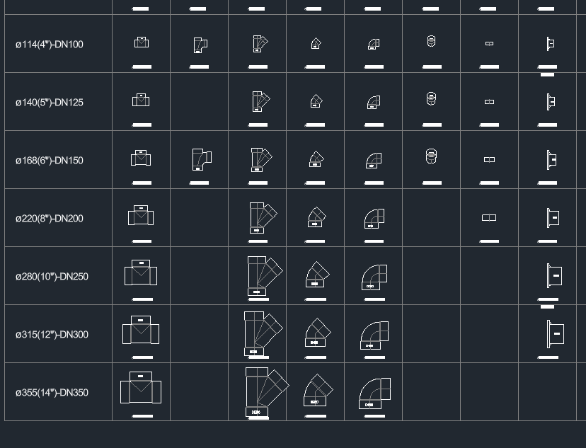
The PPR set is the most complete part of the library, with 19 fitting types: 90° elbow, 45° elbow, tee, male adapter, male adapter (union), female adapter, female adapter (union), flange, end cap, PPR union, PPR gate valve, elbow female adapter, elbow male adapter, tee female adapter, tee male adapter, socket, PPR pipe and HDPE pipe. A separate table holds reducers and reducing tees.
Sizes run through the standard PPR outside diameters: ø20, ø25, ø32, ø40, ø50, ø63, ø75, ø90, ø110, ø125, ø140, ø160 and ø200 mm, covering DN15 to DN200. This suits domestic hot and cold water distribution in villas, apartments and hotel risers.
3. Valves and Instruments
The valve set covers 17 items in sizes from DN15 to DN300:
- Isolation: gate valve, butterfly valve, brass ball valve, uPVC ball valve
- Non-return: swing check valve, wafer double check valve, silent check valve, foot valve
- Control: pressure reducing valve, float valve, automatic air vent valve
- Line accessories: flexible connector, Y-strainer, water meter
- Instruments: pressure sensor, thermal sensor, pressure gauge
This is the set for pump schematics, tank connections, booster set details and chilled water coil hook-ups.
4. uPVC Fittings
The uPVC set covers tee, tee-bend, wye, 45° elbow, 90° elbow, cleanout, end cap, flange, female adapter, male adapter, P-trap and uPVC pipe, in 15 sizes from DN15 to DN350. Use it for drainage, soil and waste stacks, and irrigation layouts.
5. AC Condensate PVC Fittings
A separate table is set up for split AC and FCU condensate drainage:
- 45° and 90° elbows from DN15 to DN200
- Reducers: DN20×15, DN25×20, DN25×15 and DN32×25
- Reducing and equal tees: DN20×15, DN25×20, DN25×15, DN32×25, DN20 and DN25
- A second tee type in DN15 and DN20
- A 45° Y in DN50×40
Condensate disposal from cooling coils is governed by SBC 501 (Saudi Mechanical Code). Show the traps, slopes and discharge points clearly on the drawing, because consultants routinely comment on them.
6. MEP Symbol Legends
The file also includes five ready-made legend tables:
- Electrical: one-way, two-way, intermediate and dimmer switches; single, double, waterproof and emergency socket outlets; LED downlights, spotlights, chandelier and emergency exit signs.
- Low voltage: TV, telephone, data, LAN, fax and door phone outlets.
- Conduit and fittings: junction boxes, conduit runs and bends, and apartment panels.
- Mechanical supports: cable trays, cable ladders, their elbows and tees, and supports.
- General: direction symbols, up/down arrows, power points and height-above-floor tags.
How the Dynamic Views Work
Each block holds all four views inside one definition. Insert the block, click it, and pick Plan, Side, Front or Top from the visibility grip. You do not need separate blocks for the floor plan and the riser diagram. A gate valve on a plan and the same valve on a section elevation are one block with a different state selected.
This keeps the block count low and makes data extraction reliable. Running DATAEXTRACTION on a drawing gives one clean line per fitting type and size for your bill of quantities, instead of four differently named blocks for the same item.
Why Integrated Wipeout Matters
A fitting drawn over a pipe line normally leaves the line running straight through the symbol. Most draughtsmen then trim or break the pipe at every valve and fitting, which is slow and breaks again as soon as anything moves.
These blocks carry a wipeout object inside the definition, so the pipe line behind the symbol is hidden automatically. Move the valve along the pipe and the mask moves with it. Two things to check:
- Set
DRAWORDERCTLto 3 so blocks draw above existing lines. - If a wipeout frame shows when plotting, set
WIPEOUTFRAMEto 0 or 2.
Tips for Using the Library on Gulf Projects
- Match the material to the service. Steel fittings suit fire fighting to NFPA 13 (2022 edition) and NFPA 14 (2024 edition), as adopted through SBC 801. PPR suits domestic water, and uPVC suits drainage under SBC 701 (Saudi Plumbing Code).
- Keep sizes consistent with the pipe schedule. The size column uses a combined OD, inch and DN label. Keep the same format in your drawing’s pipe tags so the submittal reads consistently.
- Scale the blocks to the drawing. The blocks are drawn at a nominal symbolic size. Insert at a uniform scale suited to your plot scale, and keep that scale across the whole sheet set.
- Put blocks on the right layers. Before inserting, set layers such as P-DOMW-FITT, P-SANR-FITT or F-PROT-FITT, so fittings can be frozen or recoloured by discipline.
File Details
- Format: DWG
- Software: AutoCAD 2018 and later
- File size: 31.2 MB
- Block type: Dynamic blocks with visibility states and integrated wipeout
- Units: Millimetres
Checking…
Related Downloads
For individual sets in more detail, see our PP-R fittings, valve CAD blocks and black steel pipe dynamic blocks downloads.
Frequently Asked Questions
Which AutoCAD version do I need to open this file?
The file is saved in AutoCAD 2018 format, so it opens in AutoCAD 2018 and every later release. Dynamic block grips need full AutoCAD. AutoCAD LT supports inserting and using dynamic blocks, but not editing their definitions.
How do I switch between plan, side, front and top views?
Select the inserted block and click the triangular visibility grip. A list of the available views appears; pick the one you need. You can also change it from the Custom section of the Properties palette.
Why does the pipe line disappear behind the fitting?
Each block contains a wipeout that masks whatever is drawn beneath it. If the pipe still shows through, select the block and use Draw Order › Bring to Front.
Are the steel pipe sizes suitable for fabrication?
No. The outside diameters are rounded nominal values for drafting. For spool drawings and fabrication, use exact dimensions from ASME B36.10M for carbon steel or ASME B36.19M for stainless steel.
Can I use these blocks in a Civil Defence submittal?
Yes, the symbols suit fire fighting shop drawings, provided your legend sheet explains each symbol and the valve types match your approved material submittal. Keep supervisory valves, check valves and pressure gauges clearly identifiable on the riser diagram.


i like it