
Valve CAD Blocks DWG Free Download – Gate, Ball & Butterfly
Valve CAD blocks are the most repeated element in any MEP shop drawing. Chiller room, pump room, fire fighting riser, plumbing manifold — wherever you go, you end up drawing gate valves, butterfly valves, check valves and balancing valves again and again. This post gives you 8 complete valve block sheets in a single DWG file, covering DN15 to DN600 in plan, elevation and section views. Everything opens in AutoCAD 2007 and every version above it.
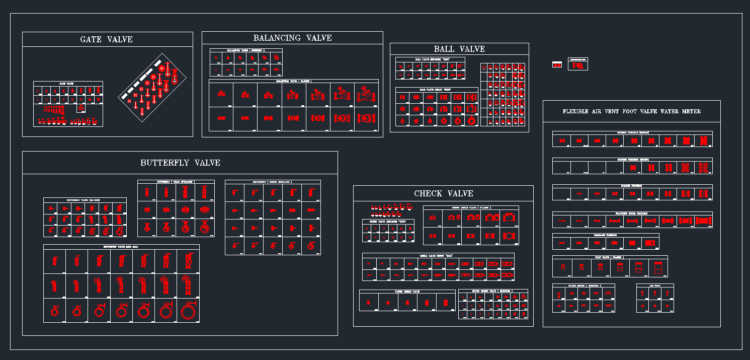
What You Get in This DWG File
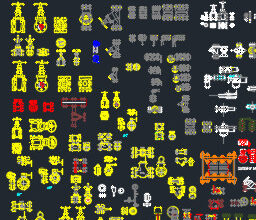
The file contains 9 sheets and each sheet covers one valve family. Every block already carries its size tag (DN or inch), and most valves are drawn in two or three views — plan (top), elevation (front) and end view — so you can use them directly in both section drawings and riser diagrams.
| Sheet | Valve Type | Size Range | End Connection |
|---|---|---|---|
| 1 | Gate Valve | DN15 – DN200 | Screwed & Flanged |
| 2 | Balancing Valve (DRV) | DN15 – DN300 | Screwed & Flanged |
| 3 | Ball Valve (Bronze & Iron) | DN15 – DN200 | Screwed & Flanged |
| 4 | Butterfly Valve (Lever & Gear) | DN65 – DN600 | Wafer & Lug |
| 5 | Check Valve (Swing & Wafer) | DN15 – DN300 | Screwed & Flanged |
| 6 | Flexible Connector, Air Vent, Foot Valve, Water Meter | DN25 – DN300 | Flanged & Screwed |
| 7 | Pressure Relief Valve | Detailed flanged assembly | Flanged |
| 8 | Pressure Reducing Valve (Pilot Operated) | Detailed 2-view assembly | Flanged |
| 9 | Master Sheet (everything in one layout) | — | — |
1. Gate Valve CAD Blocks (DN15 – DN200)
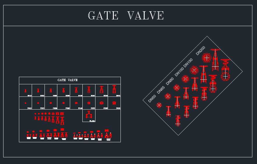
This sheet has two sets. The first set is orthographic (top view plus front view with size tags) for use in floor plans and sections. The second set is pictorial (DN50, DN65, DN80, DN100, DN150, DN200), which works well in riser diagrams and presentation drawings.
In practice, valves up to DN50 (2″) are generally bronze screwed gate valves, and DN65 and above are cast iron or ductile iron flanged. Flange drilling follows ANSI B16.5 Class 150 or EN 1092-1 PN16, and face-to-face length follows ASME B16.10. Fire fighting systems use OS&Y (Outside Screw & Yoke) rising stem gate valves because NFPA 13 requires water supply control valves to be of the indicating type and electrically supervised with a tamper switch. When you insert the block, leave clear space for the stem travel — otherwise it fouls the ceiling on site.
2. Balancing Valve CAD Blocks (Screwed & Flanged)
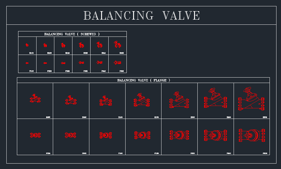
Double Regulating Valves (DRV) are used for flow balancing in chilled water and LPHW systems. The blocks clearly show the pressure test point nipples and the handwheel with its position indicator, which makes them very useful in AHU and FCU branch details.
Always show the balancing valve on the return line unless the project specification says otherwise, and keep a minimum of 5×D straight pipe upstream — without it the flow measurement will read wrong. Note that the valve can be smaller than the pipe, because selection is based on Kv and design flow, not on pipe diameter. Include valve size, design flow (l/s) and pre-set value columns in your schedule table; the TAB contractor commissions the system from exactly that data.
3. Ball Valve CAD Blocks (Bronze & Iron)
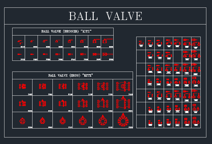
Bronze screwed ball valves up to DN50 are the standard choice for domestic water and small branch isolation. These blocks include the lever handle swing, which matters more than it looks — lever operating space is usually the first thing to clash during coordination near shafts and ducts. The iron flanged set also includes the end view with bolt circle, which adds good detail to pump room sections.
One design note: a ball valve is meant for isolation, not throttling. A partially open ball valve damages its seat quickly and generates noise. Show a globe or butterfly valve where throttling is required.
4. Butterfly Valve CAD Blocks (DN65 – DN600)
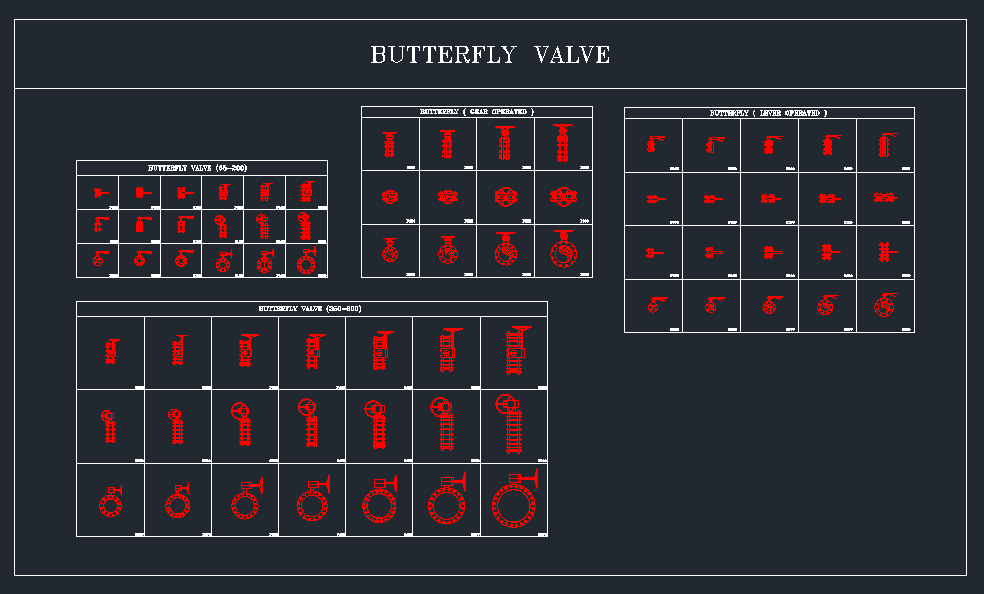
This is the most used sheet of the set, because butterfly valves are the backbone of both chiller plant rooms and fire pump rooms. The blocks are drawn in three views — plan, elevation and disc face with bolt holes.
Rule of thumb: lever operation works up to DN200, and DN250 and above should be gear operated, since manual lever torque is no longer practical at that size. The gearbox handwheel radius is already included in the block, which makes it easy to show a 600–750 mm clear access aisle in the plant room layout. In fire service, lug type is preferred over wafer type so the valve stays tight on the line even when downstream piping is dismantled, and the valve should be UL/FM listed with a supervisory switch.
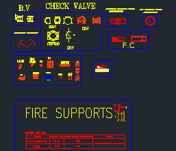
5. Check Valve CAD Blocks (Swing, Wafer & Screwed)
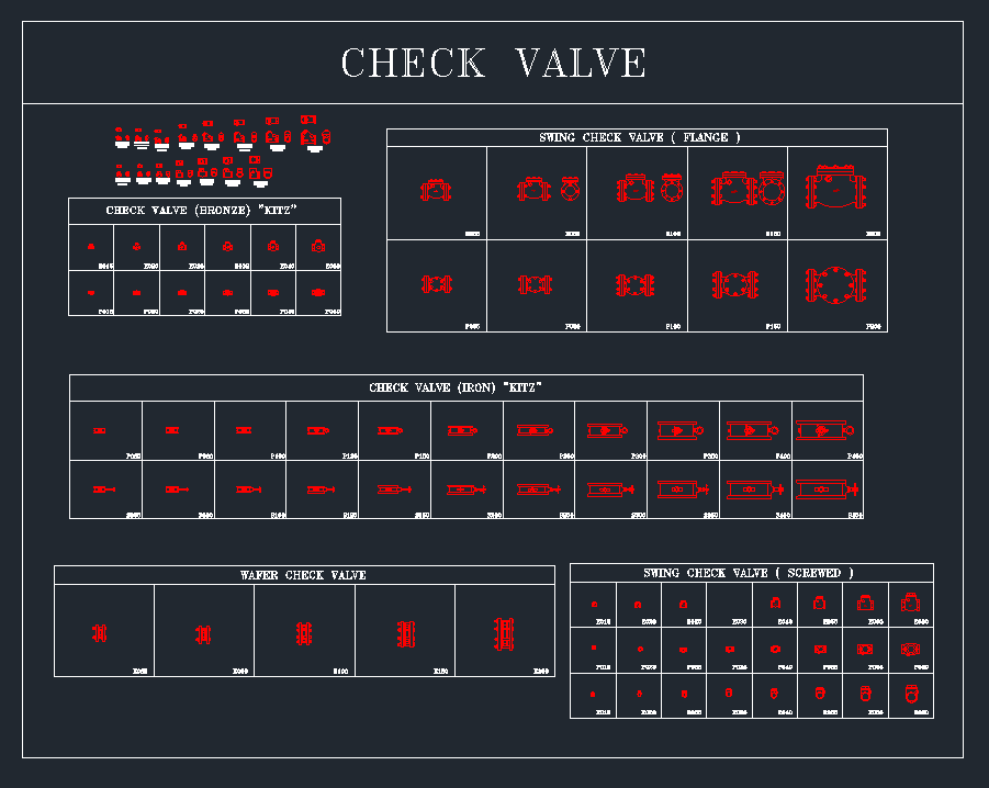
Showing the wrong check valve orientation at the pump discharge is a very common drawing mistake, so always keep the flow arrow visible. Swing check valves work best in horizontal lines; in vertical lines they should only be used with upward flow, and even then a spring-loaded silent check is better because it significantly reduces water hammer when the pump trips.
NFPA 20 requires a check valve at the fire pump discharge, and a wafer type dual-plate check saves length where the pump room is tight. For detailed check valve blocks and installation notes, see the dedicated post: Check Valve CAD Blocks Free Download.
6. Flexible Connector, Air Vent, Foot Valve & Water Meter
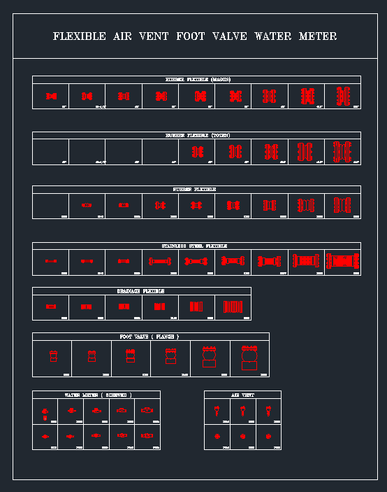
This sheet is a lifesaver for pump room detail drawings. A rubber twin-sphere flexible connector goes on both the suction and discharge of the pump to absorb vibration and minor misalignment — draw it right at the pump nozzle, and mark the control rods or anchor point immediately after it.
Automatic air vents go at every high point of a chilled water system and at the top of AHU coils. A foot valve is used when the pump works under suction lift conditions (tank below, pump above). The water meter blocks are screwed type, used on incoming domestic supply and for sub-metering — remember to show the upstream strainer and isolation valves on both sides.
7. Pressure Relief Valve Detail
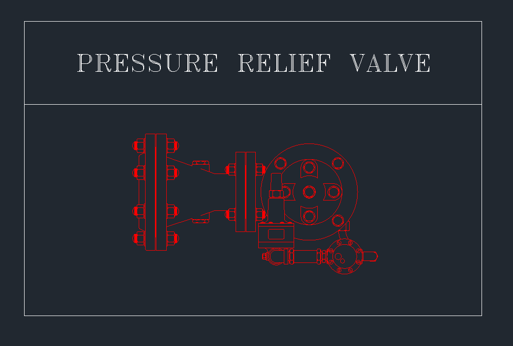
This is a high-detail block, so use it on detail sheets at 1:10 or 1:20 scale rather than on a floor plan. In a fire pump installation, NFPA 20 requires a circulation relief valve on electric motor-driven pumps, and a main pressure relief valve where the churn (shut-off) pressure could exceed the rated working pressure of the system. Its discharge must be routed through a visible waste cone to the drain, and that routing should be shown on the drawing.
8. Pressure Reducing Valve Detail (Pilot Operated)
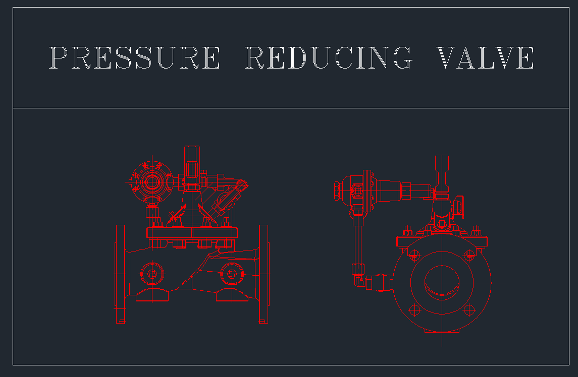
Without pressure zoning in a high-rise building, fixtures on the lower floors cannot survive 8–10 bar of static pressure. A pilot operated PRV station is typically drawn as strainer, upstream isolation valve, PRV, downstream isolation valve, pressure gauges on both sides, and a bypass line. For standpipe systems, NFPA 14 requires pressure regulation at hose connections where static pressure exceeds 12.1 bar (175 psi).
Download — Valve CAD Blocks DWG (Free)
File format: .DWG (AutoCAD 2007 compatible) · Units: mm · Layers: separate valve layer · License: free for personal and professional project use.
Checking…
How to Use These Blocks in AutoCAD
- Download and extract the file — unzip it into your project folder.
- Open the DWG and run the
UNITScommand to confirm the insertion unit is millimeters. If your drawing is set in meters, insert with a scale factor of 0.001. - Insert the block — either copy and paste (Ctrl+C / Ctrl+V), or use
ADCENTER(DesignCenter) to drag blocks straight into your drawing. For repeat use, dragging them onto a Tool Palette is fastest. - Assign the correct layer — move the block onto your project layer (for example
M-PIPE-VALVorFP-VALVE) and keep properties ByLayer so plot styles stay consistent. - Set the scale — scale symbol blocks to suit your drawing scale (a symbol sized for 1:100 will look small in a 1:50 plan), while detail blocks such as the PRV and relief valve stay at real size.
- Build your own template — save all frequently used blocks into a company DWT template, and run
PURGEbefore saving to drop unused blocks and cut file size dramatically.
Shop Drawing Tips From the Field
- Give every valve a unique tag (for example
GV-CHW-01) and put a valve schedule table on the drawing — consultant approval moves much faster. - Never show a valve tight against a wall, beam or ceiling. Leave at least 300 mm clearance for the handwheel or lever and 600 mm of access in front of it.
- A butterfly valve sits between two flanges — do not give it a gate valve’s spool length, or the pipe will come up short on site.
- Keep valve blocks on one layer and never explode them. Once exploded, a global symbol update across all valves becomes impossible.
- Run
-PURGEandAUDITbefore every approval submission.
Frequently Asked Questions
Are these valve CAD blocks free?
Yes, these blocks are completely free to download and you can use them in both personal practice and professional project drawings. Reselling the file is not permitted.
Which AutoCAD version will open this file?
The file is saved in AutoCAD 2007 format, so it opens in AutoCAD 2007 through the latest release, and also in alternatives such as BricsCAD, ZWCAD, GstarCAD and DraftSight.
What units are the blocks drawn in?
All blocks are drawn in millimeters, which is the standard for Gulf region and most international MEP projects. When inserting into a meter-based drawing, use a scale factor of 0.001.
Do these include 3D valve models?
No, these are all 2D blocks — plan, elevation and end views. They are made for shop drawings, sections and riser diagrams, not for BIM modelling.
How does a gate valve differ from a butterfly valve on a drawing?
A gate valve has a much longer face-to-face dimension and its rising stem needs clearance above it, while a wafer or lug butterfly valve sits between two flanges and takes very little length — but its gearbox or lever needs clearance at the side. Both need different clearances shown during layout coordination.
Is the balancing valve always the same size as the pipe?
Not necessarily. A balancing valve is selected on required flow and available pressure drop (Kv value), so it is often one size smaller than the pipe. Show the reducer followed by the valve on the drawing.
Thank you for sharing this useful information. I Found the article very helpful and informative. I look forward to learning more about MEP CAD and design.