Check Valve CAD Blocks DWG Free Download (Swing, Wafer, Bronze & Iron)
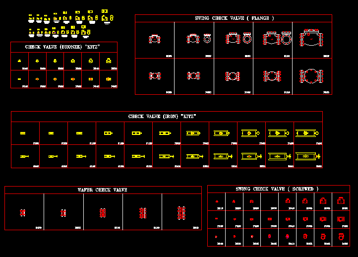
This DWG file contains a complete library of professionally drafted check valve AutoCAD blocks, covering every type you need for plumbing, HVAC and fire fighting shop drawings — swing check valves (flanged & screwed), wafer check valves, bronze and iron body valves from DN15 up to DN450.
Each valve is drawn to catalog dimensions in elevation (E), plan (P) and section (S) views, so your valve schedules and coordination drawings stay dimensionally accurate. Blocks follow standard manufacturer proportions (KITZ-pattern bronze and iron ranges) and can be inserted directly into your project drawings without modification.
What’s Inside the DWG File?
- Bronze screwed check valves — DN15 to DN80 (elevation + plan views)
- Swing check valves, flanged — DN65 to DN200 (elevation + plan views)
- Swing check valves, screwed — DN18 to DN80 (elevation, plan + isometric-style views)
- Iron body check valves — DN65 to DN450 (plan + section views)
- Wafer check valves — DN65 to DN200
- Clean DWG structure, blocks drawn 1:1 in millimetres
- View prefixes labelled per size (E = elevation, P = plan, S = section)
Technical Specifications
| File Type | AutoCAD DWG |
| Block Type | 2D Valve Symbols & Details |
| Valve Types | Swing (flanged & screwed), Wafer, Bronze, Iron |
| Size Range | DN15 – DN450 (½″ – 18″) |
| Views Included | Elevation, Plan, Section |
| Version Compatibility | AutoCAD 2010 and above |
Check Valve Size Coverage
| Valve Type | Sizes (DN) | Typical Use |
|---|---|---|
| Bronze screwed check | 15 – 80 | Domestic water branches, water heaters |
| Swing check (flanged) | 65 – 200 | Pump discharge, chilled & condenser water |
| Iron body check | 65 – 450 | Large mains, fire pumps, district cooling |
| Wafer check | 65 – 200 | Tight plant rooms, booster sets |
Why Use These Check Valve Blocks?
- Save time — stop redrawing valves for every shop drawing
- Dimensionally accurate valve schedules and coordination sections
- All views (elevation/plan/section) in one file for plans, risers and details
- Consistent valve symbols across your whole project drawing set
Who Should Download?
- MEP Draftsmen & BIM Technicians
- Plumbing & Fire Fighting Design Engineers
- HVAC Engineers preparing plant room details
- QA/QC Teams verifying valve schedules
- Trainee Engineers building their CAD libraries
How to Use the Blocks
Open the DWG, select the block for your valve size and view, press Ctrl+Shift+C (copy with base point), then paste into your project drawing. Blocks are drawn at 1:1 in millimetres, so they inherit your current layer properties on insert. The label under each block tells you the view and size — for example, E100 is the elevation view of the DN100 valve, P100 the plan view, and S100 the section.
Download Check Valve CAD Blocks – DWG
Click below to download the complete check valve AutoCAD block library in DWG format.
Checking…
Don’t have AutoCAD installed? See our guide: 5 Free Ways to Open DWG Files Without AutoCAD.
Related Posts
- AutoCAD Drainage Fittings Section & Typical Details DWG Free Download
- Fire Fighting Dynamic Blocks & Standard Details DWG Free Download
- Basement Water Supply Shop Drawing Free Download
Final Words
This check valve block library is part of a real-world drafting collection used in professional MEP projects. Whether you are preparing plumbing risers, pump room details or fire fighting layouts, having every check valve size and view in one DWG keeps your drawings fast and consistent. Download it, add it to your CAD toolkit, and explore our free online MEP calculators for pipe and pump sizing.