Fire Fighting System Design & Calculation (NFPA) — A to Z
This is a complete fire fighting system design and calculation guide for MEP engineers and draftsmen, based on the NFPA standards used on Gulf and international projects. It covers the applicable codes, system types, hazard classification, sprinkler design criteria, the full hydraulic calculation procedure, and the sizing of the fire pump and water tank — with the key formulas and reference tables you need from A to Z.
1. Applicable codes & standards
| Standard | Covers |
|---|---|
| NFPA 13 | Installation of sprinkler systems |
| NFPA 14 | Standpipe and hose systems |
| NFPA 20 | Stationary pumps for fire protection |
| NFPA 22 | Water tanks for private fire protection |
| NFPA 24 | Private fire service mains and appurtenances |
| NFPA 25 | Inspection, testing & maintenance of water-based systems |
In the Gulf, projects also follow the local Civil Defence codes, which are largely based on NFPA.
2. Fire fighting system types
The main water-based and special systems used in buildings:
| System | Where used |
|---|---|
| Wet pipe sprinkler | Heated buildings — pipes always charged (most common) |
| Dry pipe sprinkler | Areas at risk of freezing — pipes filled with air |
| Pre-action sprinkler | Water-sensitive areas (data centres, archives) |
| Deluge sprinkler | High-hazard areas — open heads, all discharge together |
| Foam water sprinkler | Flammable-liquid hazards (Class B) |
| Standpipe & hose | Hose connections for fire brigade / occupants |
| Water spray | Transformers, vessels, special hazards |
| Fire hydrant | External fire brigade water supply |
3. Main components
| Component | Component |
|---|---|
| Sprinkler head | Pressure gauge |
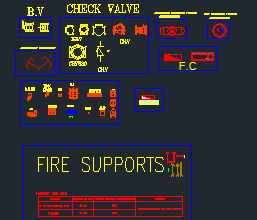
| Pipe work | Check valve |
| Control valve | Alarm valve |
| Fire pump | Pressure switch |
| Jockey pump | Flow switch |
| Fire water tank | Hose cabinet (FHC) |
4. Hazard classification (NFPA 13)
Hazard classification governs the design density, area of operation and system demand.
| Classification | Description | Examples |
|---|---|---|
| Light Hazard (LH) | Combustible contents with low fire load | Offices, classrooms, hotels, churches |
| Ordinary Hazard (OH) | Moderate fire load contents | Residential, retail, warehouses |
| Extra Hazard (EH) | High fire load, combustible materials | Industrial, bulk storage, process areas |
5. Sprinkler design criteria (NFPA 13)
- Design density (gpm/ft²) depends on the hazard classification.
- Area of operation — the maximum area over which sprinklers are assumed to operate.
- Minimum pressure at the sprinkler: 7 psi (0.5 bar).
- Discharge coefficient (K) — refer to UL/FM sprinkler data.
Where Q = discharge (gpm), K = discharge coefficient, P = pressure at the sprinkler (psi).
6. Sprinkler spacing guide (NFPA 13)
| Hazard | Max spacing | Max coverage per head | Area of operation |
|---|---|---|---|
| Light Hazard | 15 × 15 ft | 225 ft² | 1500 ft² |
| Ordinary Hazard (Gr. 1) | 15 × 15 ft | 130 ft² | 1500 ft² |
| Ordinary Hazard (Gr. 2) | 12 × 12 ft | 130 ft² | 1500 ft² |
| Extra Hazard (Gr. 1) | 12 × 12 ft | 100 ft² | 2500 ft² |
| Extra Hazard (Gr. 2) | 12 × 12 ft | 100 ft² | 2500 ft² |
Spacing may be reduced for obstructions, construction features and in-rack sprinklers per NFPA 13. Always confirm against the current edition.
7. Hydraulic calculation procedure (10 steps)
- Determine the hazard classification and design criteria.
- Select the area of operation and compute the design flow.
- Select the sprinklers and obtain the K-factor.
- Determine the required pressure at the sprinklers (min. 7 psi).
- Draw the hydraulic schematic of the system.
- Calculate friction loss in pipes using Hazen-Williams.
- Add minor losses (fittings, valves, devices).
- Determine the total system demand (flow and head).
- Check the available water supply (flow & pressure).
- Finalize pipe sizes, pump selection and submit the design.
8. Fire pump sizing (NFPA 20)
The fire pump flow is the total system demand, including hose allowance where required:
Where the head terms are: static (static lift + elevation), friction (total friction loss in the system), residual (residual pressure at the topmost outlet, usually 7 psi) and margin (about 10% extra, recommended).
A fire pump must meet three points on its performance curve under NFPA 20: 100% rated head at 100% rated flow, not less than 65% rated head at 150% rated flow, and not more than 140% rated head at churn (no flow).
9. Fire water tank sizing (NFPA 22)
Where V = tank capacity (gallons or m³), Q = total fire flow demand (gpm or m³/hr), T = required duration (min).
| Occupancy | Typical duration |
|---|---|
| Light Hazard | 60 min |
| Ordinary Hazard | 90 min |
| Extra Hazard | 120 min |
| Storage / Industrial | 120 – 180 min |
Provide about 10% extra capacity as reserve.
10. Standpipe & hose system (NFPA 14)
| Class | Use | Outlet | Flow |
|---|---|---|---|
| Class I | Fire department / trained personnel | 2½ inch | 250 gpm (946 L/min) |
| Class II | Building occupants | 1½ inch | 100 gpm (379 L/min) |
| Class III | Both fire department & occupants | 2½ & 1½ inch | As above |
System pressure at the most remote 2½” outlet shall not be less than 100 psi (6.9 bar) at the required flow.
11. Fire hose cabinet (FHC)
Typical components: hose reel (30 m × 25 mm), 2.5″ inlet connection, 1.5″ nozzle, hose valve, glass break / hammer and an instruction plate. Install the FHC so that no point in the building is more than 30 m travel distance from a cabinet.
12. Zone control valve (ZCV)
Each zone is fed from the riser through a ZCV assembly that typically includes a pressure gauge, a check valve and the zone control valve, with a flow switch that signals the fire alarm panel (FACP) when water flows in that zone.
13. Pressure reducing valve (PRV)
A PRV reduces high upstream pressure to a lower downstream set pressure. It is installed where downstream pressure would exceed the allowable limit (usually above 175 psi). The set pressure is fixed as per the design requirement.
14. Pipe sizing & velocity (Hazen-Williams)
Use the Hazen-Williams formula for head-loss calculation:
Where h₌ = head loss (m), L = pipe length (m), Q = flow (m³/s), C = Hazen-Williams coefficient, d = inside diameter (m).
15. Typical pipe materials
| Material | Standard | Use | Remarks |
|---|---|---|---|
| Carbon steel (black) | ASTM A53 / A795 | Mains & risers | Most common |
| CPVC | ASTM F441 | Sprinkler branches | Corrosion resistant |
| Galvanized steel | ASTM A53 | Older installations | Not preferred now |
| Stainless steel | ASTM A312 | Special applications | High corrosion resistance |
| Ductile iron | AWWA C151 | Underground mains | High strength |
16. Fire pump room layout (typical)
A typical pump room runs from the fire water tank through a suction line with a foot valve & strainer and an eccentric reducer into the fire pump on a common base frame, then out through an OS&Y gate valve and check valve to the discharge line feeding the system. Maintain access and clearance around the set for testing and maintenance.
17. Fire pump testing (NFPA 20)
- Hydrostatic test — 1.5 times the working pressure.
- Performance (pump) test against the three curve points — churn, rated and 150% flow.
- Suction pressure test.
- Pressure relief valve test.
- NPSH test (if required).
- Record all test results and submit the report.
18. Testing & commissioning checklist
| Check | Check |
|---|---|
| Visual inspection | Jockey pump test |
| Hydrostatic test | Main fire pump test |
| Flushing | Backflow preventer test |
| Sprinkler flow test | Standpipe test |
| Alarm valve test | Hose reel test |
| Pressure switch test | FHC accessibility check |
| Flow switch test | Final system handover |
19. Common design mistakes to avoid
- Undersized pipes & pumps.
- Ignoring elevation / pressure requirements.
- Incorrect hazard classification.
- Excessive pipe velocity (> 3 m/s in mains).
- No consideration for future expansion.
- Improper valve locations and missing isolation valves for maintenance.
- Missing hose allowance in the demand.
- Inadequate water supply duration.
- Poor coordination with other disciplines.
20. Coordination tips
- Coordinate with architectural, structural and MEP drawings.
- Ensure adequate water supply (flow & pressure).
- Maintain minimum clearance around the tank & pump for access.
- Provide drainage & ventilation in the pump room.
- All valves shall be accessible and labelled.
- Support all pipes per NFPA 13; install flexible connections at pump suction & discharge.
- Provide test & drain valves at low points.
- Ensure compliance with the local AHJ requirements.
Conclusion
Fire fighting design comes down to four linked steps: classify the hazard, set the sprinkler density and area of operation, run the hydraulic calculation, then size the pump and tank — all within the NFPA framework and the local Civil Defence code. A fire fighting system is a life-safety system: design it right, install it right, and maintain it right. Always confirm the final design against the project specification and the authority having jurisdiction (AHJ).
Disclaimer: This guide is for educational and reference purposes. Always design and verify fire protection systems in accordance with the current NFPA standards, local Civil Defence codes and the AHJ.