HVAC Ducting and Chilled Water System Shop Drawing DWG Free Download
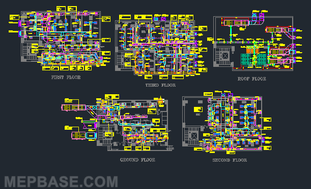
If you are preparing HVAC shop drawings for high-rise or commercial projects, a ready-made HVAC chilled water system DWG with ducting and piping layouts can save you hours of drafting.
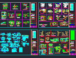
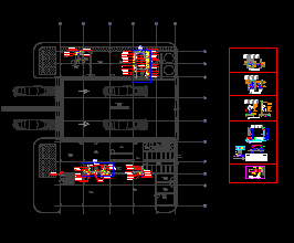
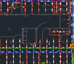
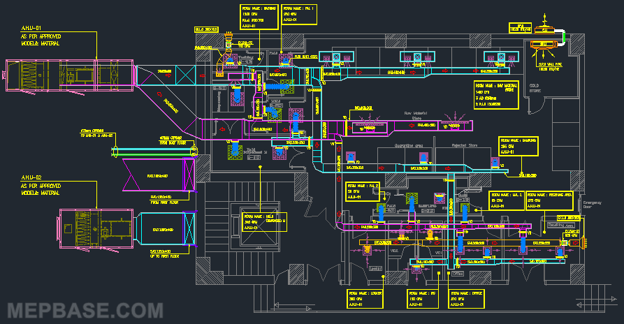
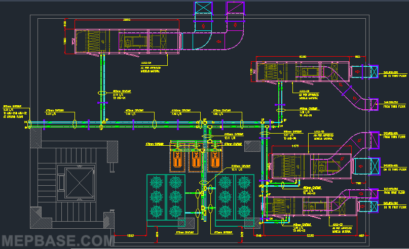
This DWG file includes complete supply and return air duct layouts, along with chilled water piping system drawings covering FCU and AHU connections. It follows standard Gulf (KSA/UAE) drafting practices, making it a reliable reference for both freshers and professionals.
What’s Inside the DWG File?
- Supply, return and exhaust duct layouts
- VCD, FD and access door installation details
- Flexible duct connections to grilles and diffusers
- Complete chilled water supply and return piping system
- FCU and AHU connection details
- Pipe insulation and hanger details
- Sections for better coordination
Common Abbreviations Used in the Drawing
| Abbreviation | Meaning |
|---|---|
| SA / RA / EA | Supply air / Return air / Exhaust air |
| CHWS / CHWR | Chilled water supply / Chilled water return |
| FCU | Fan coil unit |
| AHU | Air handling unit |
| VCD | Volume control damper |
| FD | Fire damper |
| AD | Access door |
| BOD | Bottom of duct (level) |
| BOP | Bottom of pipe (level) |
Who Can Use This DWG File?
- HVAC draftsmen working on duct and chilled water systems
- MEP engineers preparing coordination and shop drawings
- Students and freshers learning HVAC drafting standards
- Contractors and consultants for tender and as-built submissions
Why Use This DWG File?
Using this drawing will help you:
- Save drafting time
- Maintain professional drawing standards
- Get consultant approval faster
- Understand practical site installation details
Shop Drawing Checklist: What Consultants Check
Before you submit an HVAC ducting and chilled water shop drawing, check these points. They are the most common reasons for comments from the consultant.
Ducting
- Duct sizes match the approved design and are marked on every run
- Bottom of duct (BOD) levels shown and coordinated with ceiling height
- VCDs on every branch, and fire dampers at every fire-rated wall or slab crossing
- Access doors at every fire damper and other serviceable component
- Flexible duct lengths kept short at diffusers and grilles
- Diffuser and grille sizes and airflows shown and matching the schedule
Chilled water piping
- CHWS and CHWR pipe sizes marked, with flow direction arrows
- Isolation valves, strainers, balancing valves and 2-way control valves at each FCU and AHU
- Air vents at high points and drains at low points
- Insulation and hanger details as per the project specification
- Pipe levels (BOP) coordinated with ductwork, cable trays and sprinkler pipes in sections
To check sizes on your own project, use the Duct Size Chart PDF, the Online Ductulator, Chilled Water Pipe Sizing and the CHW Pipe Calculator.
Download HVAC Ducting + Chilled Water System Shop Drawing DWG Free
This DWG file is ready to use and can be directly applied in your HVAC shop drawings, tender submissions, or coordination drawings. It contains both ducting and chilled water piping details based on Gulf standards. Always adapt sizes, levels and details to your project’s approved design and specification.
Checking…
Related Design Guides
- External Static Pressure (ESP) Calculation for AHU and FCU
- Chilled Water Pump Head Calculation
- Cooling Coil Selection
- VAV Box Sizing and Selection
Related CAD Resources
- HVAC Dynamic Blocks and Equipment Installation DWG Free Download
- HVAC Installation Details
- AutoCAD Blocks for HVAC Systems Design DWG Free Download
- AutoCAD Daikin Fan Coil Unit (FCU) Block Library DWG Free Download
Frequently Asked Questions
What is included in an HVAC shop drawing?
Duct and pipe layouts with sizes and levels, equipment locations, dampers, valves and access doors, installation details, and sections showing coordination with other services.
What do CHWS and CHWR mean?
CHWS is chilled water supply, the cold water going to the coils. CHWR is chilled water return, the warmer water going back to the chiller.
Can I use this DWG directly on my project?
Use it as a reference and starting point. Sizes, levels and details must follow your project’s approved design drawings, specification and consultant standards.
Why are VCDs and fire dampers shown separately?
A VCD (volume control damper) is used to balance airflow, while an FD (fire damper) closes automatically to stop fire spreading through a fire-rated wall or slab. They do different jobs and both must be shown.