
Electrical Typical Details DWG: Cable Tray, Busduct, Generator & Earthing
If you’re working on MEP coordination or electrical shop drawings, this set of electrical typical details in DWG format is a must-have resource for consultants, draftsmen and engineers.
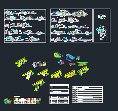
It covers the details other packages often skip: busduct and earth bar arrangements, generator and fuel tank sections, CDU isolator connections and a complete electrical room detail, along with cable tray supports, power outlets, fire alarm mounting and exit lighting.
Whether you’re preparing BOQs, IFC or shop drawings, or need references for an electrical tender submission, these details save time and improve accuracy.
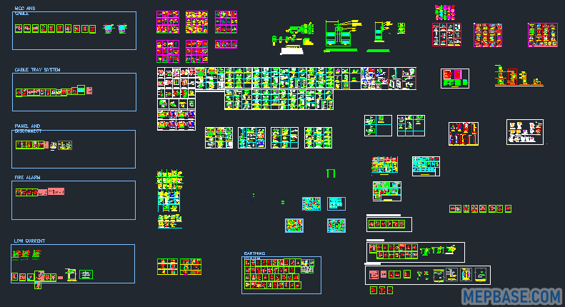
What’s Inside the Electrical Typical Details DWG?
- Cable tray and trunking installation
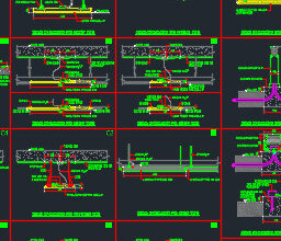
- Power outlet installation (with and without false ceiling)
- Busduct and earth bar typical details
- Lighting fixture installation
- Exit light and fire alarm device mounting
- Generator and fuel tank sections
- CDU isolator switch connections
- Support hangers for cable systems
- Single door electrical room detail
- Test point and earthing system details
Each block and section is ready to edit and scale into your project. The drawings are arranged in a clear layout with annotations and layer-based detailing.
Electrical Installation Notes
Check these points when you adapt the details to your own project:
- Cable tray: space supports according to the tray manufacturer’s load tables, bond all tray sections for earth continuity, and fire-stop the tray wherever it passes through a fire-rated wall or slab.
- CDU isolators: install a weatherproof isolator next to each outdoor condensing unit, within sight of the unit, so it can be safely isolated during maintenance.
- Mounting heights: dimension outlets, switches and fire alarm devices from the finished floor level, following the project specification and architectural drawings.
- Earthing test points: keep earth test points and test links accessible so the earth resistance can be measured during periodic inspections.
Key Use Cases
- Electrical shop drawings for residential and commercial buildings
- MEP design coordination
- Consultant or contractor drawing submittals
- Education and training
- BOQ extraction and block referencing
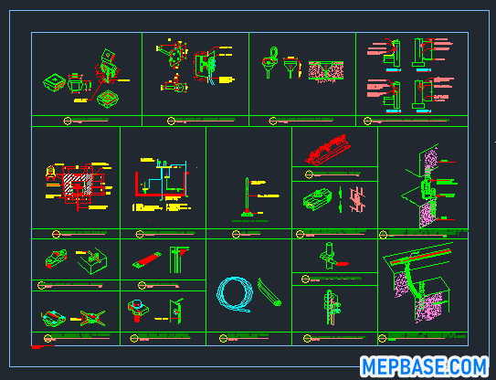
Why This Drawing Set Is Valuable
- Real project practice: based on details used on Gulf (KSA/UAE) projects
- Easy to edit: organised for quick AutoCAD editing
- Clear drawings: each detail is named, layered and labelled
- Dynamic blocks: save time on repetitive tasks
Electrical Typical Details DWG Free Download
Download the full set below. These details will cut your drafting time and help you get consultant approval faster.
Checking…
Related Downloads
- Electrical Installation Detail DWG Library
- AutoCAD Electrical Symbols DWG
- Fire Alarm Symbols DWG
- AutoCAD Lighting System Shop Drawing

This software is very useful for Electrical students