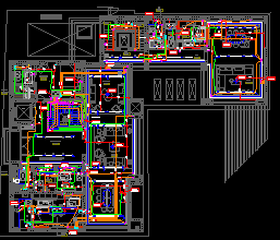
Fire Alarm System DWG – Full Building Layout (Basement to Roof)
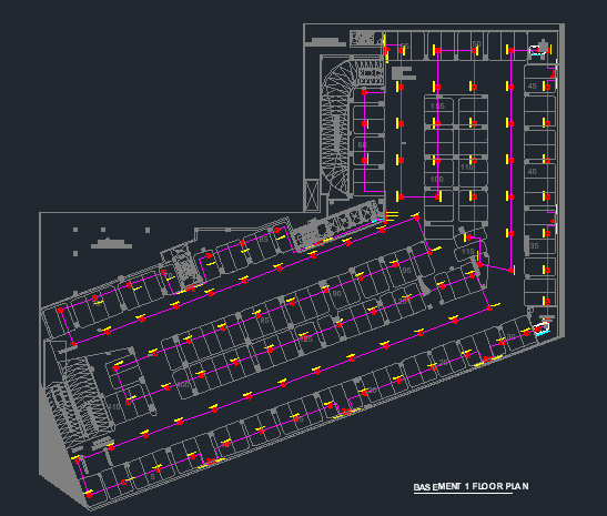
If you’re working on a fire alarm layout for a multi-storey building, especially in the Gulf region, this fire alarm shop drawing will save you hours of work. It is not a dummy sample: it is a real project-based AutoCAD drawing covering a full building, from three basement levels up to the roof. It is ideal for site engineers, MEP draftsmen and consultants who want a reference or a ready-made starting point. For the individual symbols, see our Fire Alarm Symbols DWG.
File Details
| Format | AutoCAD DWG |
| File size | 26 MB |
| Levels | Basement 3, Basement 2, Basement 1, Ground, First, Second and Roof |
| System | Addressable fire alarm, Gulf-standard symbols |
| Typical use | Mid-rise residential and commercial buildings in KSA and UAE |
Building Levels Covered
This drawing covers the full scope of a typical mid-rise building:
- Basement 3
- Basement 2
- Basement 1
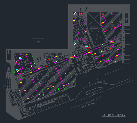
- Ground Floor
- First Floor
- Second Floor
- Roof Level
Each level is planned and detailed to common site requirements on KSA and UAE projects.
What’s Inside the DWG
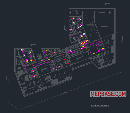
- Floor-wise fire alarm layouts with symbols and legends
- Smoke and heat detector placement based on room type
- Manual call point (MCP) locations along exit routes
- Riser diagram (where provided in the project set)
- Panel room location and loop cable routing
- Standard Gulf symbols for addressable systems
- Layer separation for easy editing
Every floor layout is clean, consultant-friendly and organised by layers.
Who This Drawing Is For
- Junior draftsmen learning fire alarm drafting
- Site engineers reviewing as-built layouts
- MEP coordinators preparing IFC or shop drawing submissions
- Freelancers building a drawing library
It is not just a visual file: it is a learning tool.
Design Checks Consultants Look For
From experience, these are the points a consultant checks first on a fire alarm shop drawing. Values are from NFPA 72, which SBC 801 references; check your project’s adopted code.
| Item | Typical requirement |
|---|---|
| Manual call point at exits | Within 1.5 m (60 in) of each exit doorway on every floor |
| Travel distance to an MCP | Not more than 61 m (200 ft) on the same floor |
| MCP mounting height | 1.07–1.22 m (42–48 in) to the operating handle |
| Smoke detector spacing | 9.1 m (30 ft) nominal on smooth flat ceilings, reduced for beams and high ceilings |
| Heat detector spacing | The listed spacing of the detector model |
Always double-check detector coverage near beams and partitions, and keep riser diagrams clear and simple. Check spacing quickly with the Smoke Detector Spacing Calculator, and size the panel batteries with Fire Alarm Battery Calculation or the Fire Alarm Battery Calculator.
How to Use This Drawing
- Download the DWG and open it in AutoCAD, or preview it in a free DWG file viewer.
- If text shows as question marks or boxes, install the missing AutoCAD SHX fonts.
- Freeze or recolour layers to match your company standard, then replace the title block.
- Adapt detector and MCP positions to your architectural plans, and recheck spacing and coverage for every room.
Need Fire Alarm Blocks?
Also check our standard fire alarm AutoCAD blocks:
- MCP (manual call point)
- Smoke and heat detectors
- Fire alarm control panel
- Editable riser diagram block
Fire Alarm Shop Drawing Free Download (AutoCAD)
Checking…
Frequently Asked Questions
What is included in this fire alarm shop drawing?
Floor-wise layouts from Basement 3 to the roof, with smoke and heat detectors, manual call points, panel location, loop cable routing, legends and layered Gulf-standard symbols for an addressable system.
Which AutoCAD version do I need?
Any recent AutoCAD version opens the DWG. Without AutoCAD, preview it in a free DWG viewer such as Autodesk Viewer.
How far should a manual call point be from an exit door?
NFPA 72 requires a manual fire alarm box within 1.5 m (60 in) of each exit doorway on each floor, with a travel distance of not more than 61 m to the nearest one.
What is the spacing of smoke detectors?
9.1 m (30 ft) nominal spacing on smooth, flat ceilings under NFPA 72, with every point on the ceiling within 0.7 × spacing of a detector. Beams, high ceilings and airflow reduce the spacing.
Can I use this drawing for my own project?
Yes, as a reference and starting point. Adapt it to your architectural plans, local code and the panel manufacturer’s requirements, and have the design checked before submission.
Have feedback or questions? Leave a comment. This site is here to help other engineers grow, just like I once needed help when starting out.
Stay safe. Draft smart.