HVAC Typical Installation Details DWG Free Download
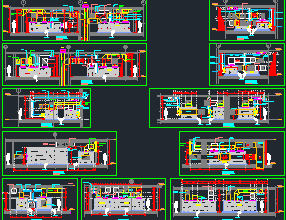
This free HVAC typical installation details DWG includes installation sections and isometric details based on real project standards from the Gulf region. These details are essential for engineers and draftsmen preparing professional HVAC shop drawings.
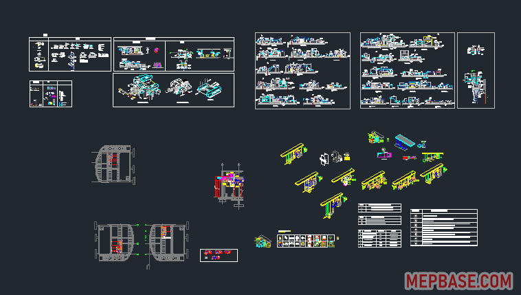
Whether you are working on a hotel, commercial or residential project, this drawing covers essential HVAC detailing such as air handling unit (AHU) installation, fan coil unit (FCU) mounting, volume control damper (VCD) positioning, duct insulation methods and hanger support details, all in both section and isometric formats.
What’s Included in the DWG File?
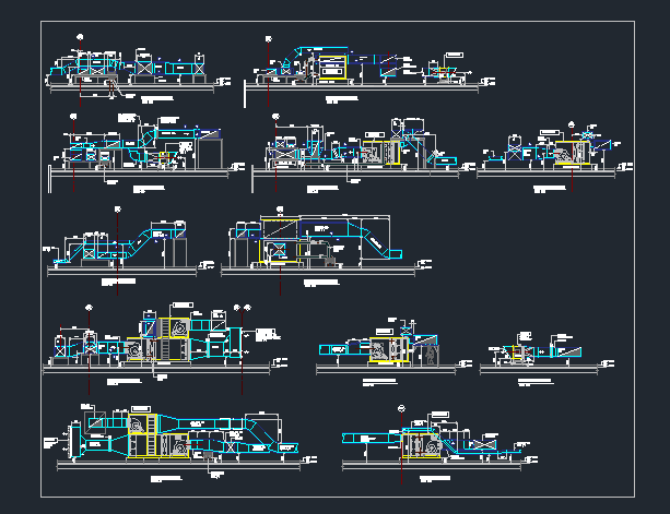
- Typical AHU section installation detail: duct connections, drain lines and insulation layers
- FCU installation detail: ceiling-mounted layout with flexible ducting
- VCD (volume control damper) placement: before the diffuser or flexible duct
- Insulated duct section: labelled with insulation thickness and material
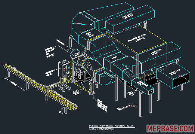
- Isometric HVAC piping layout: 3D coordination with the structure
- Hanger support detail: rods, clamps and bracket spacing
- Legend and symbols: standard Gulf MEP drafting conventions
Technical Summary
| File Format | AutoCAD DWG |
| Drawing Units | Millimetres |
| Standard | Gulf (UAE / KSA) shop drawing practice |
| File Type | Installation details and sections |
| File Size | 6 MB |
Installation Notes for HVAC Details
Use these points to check your own details when adapting the drawing:
- FCU drain: provide an auxiliary drain pan under ceiling-mounted FCUs and a trapped condensate line with enough fall to the nearest drain point.
- Access panels: show ceiling access panels for every FCU, VCD and fire damper so they can be serviced after the ceiling is closed.
- VCD location: install VCDs on branch ducts before the flexible duct, not at the diffuser neck, so balancing does not create noise at the outlet.
- Duct insulation: supply and return ducts carrying cooled air need insulation with a continuous vapour barrier, with all joints taped, to stop condensation.
- Hanger spacing: space duct and pipe hangers according to SMACNA and project specification tables, and add supports near every fitting and heavy accessory.
Why It’s Important
- Saves time for MEP consultants, engineers and draftsmen
- Acts as a training tool for freshers working on HVAC layouts
- Helps prepare BOQs and equipment installation guides
- Improves coordination between architecture, civil and HVAC services
Who Should Use This?
- MEP engineers preparing IFC and shop drawings
- Draftsmen creating HVAC coordination layouts
- Junior engineers learning HVAC site installation
- QA/QC teams checking site works against approved details
Download HVAC Typical Installation Details DWG
Click the button below to get the complete HVAC typical installation details drawing with sections and isometric views.
Checking…
Related Downloads
- AHU Plant Room Shop Drawing DWG
- HVAC Dynamic Blocks with Equipment Installation Details
- AutoCAD Blocks for HVAC Systems DWG
- Duct Sizing Chart PDF Download
Final Words
This file is more than a drawing. It is a real-world training resource for engineers working to Gulf standards. Each section is clearly labelled, so you can adapt it to your project’s sizes and specifications with minimal editing.