Fire Fighting Alarm Valve Set Detail DWG Free Download | CAD Block
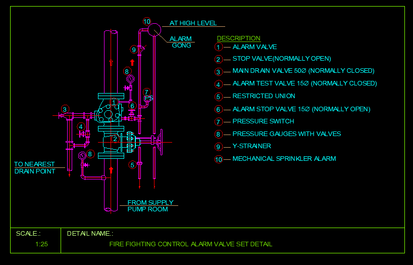
Download this professional Fire Fighting Alarm Valve Set Detail DWG block for your fire protection system designs. This comprehensive AutoCAD drawing illustrates a complete wet pipe sprinkler alarm valve assembly at 1:25 scale, featuring all essential components required for NFPA 13-compliant installations.
The alarm valve set serves as the heart of any wet pipe fire sprinkler system, maintaining system pressure while providing both mechanical and electrical alarm activation when sprinklers operate during a fire event.
What’s Included in This CAD Drawing?
This detailed fire fighting CAD block includes the complete alarm valve trim assembly with all components clearly labeled and their normal operating positions identified:
1. Alarm Valve (Main Clapper Valve)
The central component that detects water flow and directs water to alarm devices. Features an internal clapper mechanism that lifts when sprinklers activate, allowing water flow while triggering the alarm line.
2. Stop Valve – Normally Open
OS&Y (Outside Screw and Yoke) gate valve controlling the main water supply to the sprinkler system. Must remain fully open during normal operation and requires tamper supervision per NFPA requirements.
3. Main Drain Valve 50Ø – Normally Closed
A 50mm diameter valve used for system drainage during maintenance and conducting quarterly main drain flow tests to verify adequate water supply pressure.
4. Alarm Test Valve 15Ø – Normally Closed
Small 15mm valve that simulates sprinkler activation for testing alarm devices without flowing large quantities of water. Required for quarterly alarm testing per NFPA 25.
5. Restricted Union
Connects the alarm valve to the retard chamber with a calibrated orifice that prevents nuisance alarms from minor pressure fluctuations while allowing legitimate alarm activation.
6. Alarm Stop Valve 15Ø – Normally Open
Isolation valve in the alarm line allowing maintenance of alarm equipment without draining the entire sprinkler system. Must remain open during normal operation.
7. Pressure Switch
Provides electrical alarm signal to the Fire Alarm Control Panel (FACP) when water flows through the alarm valve, initiating building-wide notification and fire department dispatch.
8. Pressure Gauges with Valves
Dual gauges monitoring both supply side and system side pressures. Isolation valves allow gauge replacement without system shutdown. Gauges should read within 5 psi of each other during static conditions.
9. Y-Strainer
Protects alarm devices from debris and sediment that could clog small orifices in the alarm line. Features removable screen for annual cleaning during system maintenance.
10. Mechanical Sprinkler Alarm (Water Motor Gong)
Mounted at high level on exterior wall, this device provides local audible alarm without electrical power. Water flow spins an impeller connected to a striker producing minimum 90 dB sound at 10 feet.
Drawing Specifications
| File Format | DWG (AutoCAD 2018 Compatible) |
| Drawing Scale | 1:25 |
| Category | Fire Fighting / Fire Protection Systems |
| Standard Reference | NFPA 13, NFPA 25 |
| Application | Wet Pipe Sprinkler Systems |
Installation Requirements per NFPA 13
Proper alarm valve set installation requires careful attention to location, accessibility, and piping connections:
Location Requirements: Install in accessible valve room or pump room with minimum 36 inches clearance, adequate lighting, freeze protection in cold climates, and floor drain for test water discharge.
Supply Connection: Connect from fire pump discharge or direct city main with proper support and seismic bracing. Include backflow preventer where required by local codes.
Drain Connections: Pipe main drain and alarm line drains to visible discharge locations for proper testing and verification.
Alarm Gong Placement: Mount water motor gong at high level on exterior wall, protected from physical damage with drain piped to appropriate location.
Testing and Maintenance Schedule
Per NFPA 25, the following inspection and testing frequencies apply to alarm valve components:
| Component | Inspection | Test Frequency |
|---|---|---|
| Alarm Valve | Weekly | Quarterly / 5-Year Internal |
| Control Valves | Weekly/Monthly | Annually |
| Pressure Gauges | Monthly | 5 Years (calibration) |
| Water Motor Gong | Quarterly | Quarterly |
| Pressure Switch | Quarterly | Quarterly |
| Main Drain | Quarterly | Quarterly |
| Y-Strainer | Annually | Clean Annually |
Who Should Use This Drawing?
This free CAD block is ideal for:
- MEP Engineers designing fire protection systems
- Fire Protection Consultants preparing construction documents
- CAD Drafters creating detailed fire fighting layouts
- Contractors preparing shop drawings and submittals
- Building Owners and Facility Managers for reference
How to Use This DWG File
Simply download the DWG file and insert it directly into your AutoCAD fire fighting system layouts, riser diagrams, or construction documentation. The drawing is created with standard layers and can be easily modified to match your project requirements.
This alarm valve set detail is suitable for commercial buildings, industrial facilities, warehouses, high-rise structures, and any project requiring wet pipe fire sprinkler systems.
Download Fire Fighting Alarm Valve Set DWG
Click the download button below to get this professional fire protection CAD block absolutely free. Enhance your fire sprinkler design documentation with this ready-to-use alarm valve assembly detail.