VAV Box Sizing and Selection: Airflow, Inlet Size and Minimum Flow Explained
Pick a VAV box that is too small and the zone is noisy; pick one too large and the airflow sensor can’t control the minimum. This guide covers VAV box sizing step by step: maximum and minimum airflow, inlet size selection, pressure and noise checks, with a worked example and an inlet size table.
What a VAV box does
A variable air volume (VAV) box is a terminal unit that varies the supply airflow to one zone to match its load. A damper inside the box opens and closes based on the zone thermostat, while an airflow sensor at the inlet keeps the flow between set maximum and minimum values. This is called pressure-independent control, and it is the standard for modern systems.
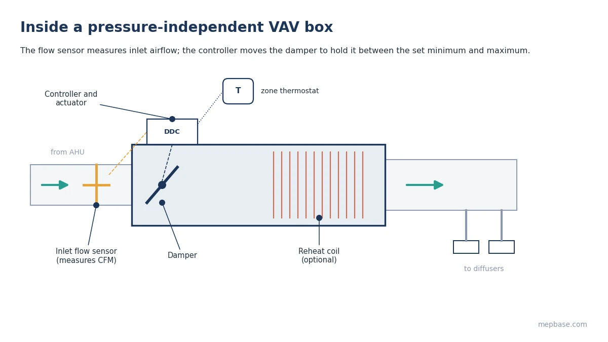
Common types are single duct cooling-only, single duct with reheat (electric or hot water coil), and fan-powered boxes (series or parallel). The sizing steps below apply to all of them.
Step 1: Maximum airflow from the zone load
The box’s maximum airflow is set by the zone’s peak sensible cooling load:
CFM = Sensible load (Btu/h) / (1.08 × ΔT)
L/s = Sensible load (W) / (1.2 × ΔT)
ΔT is the room temperature minus the supply air temperature, typically 75°F − 55°F = 20°F (24°C − 13°C = 11°C). Get the zone load from a proper load calculation, not from a whole-building rule of thumb. See the HVAC Load Calculation Guide or use the Cooling Load Calculator.
Step 2: Minimum airflow
The minimum setting is the largest of these:
- The flow needed to deliver the zone’s outdoor air requirement (ASHRAE 62.1), allowing for the outdoor air fraction of the supply air.
- The heating airflow, if the box has reheat.
- The lowest flow the airflow sensor can measure reliably. Below an inlet velocity of roughly 300 to 400 fpm (1.5 to 2 m/s), the sensor signal is too weak for stable control.
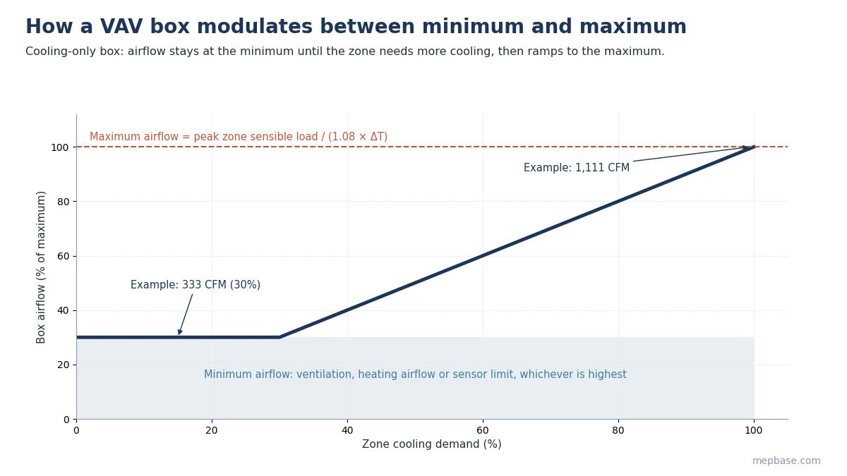
For preliminary design, 30% of maximum airflow is a common starting point. Ventilation requirements can be checked with the ASHRAE Ventilation Calculation XLS.
Step 3: Select the inlet size
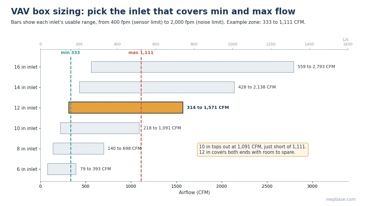
Pick the inlet size that keeps velocity at maximum flow around 1,500 to 2,000 fpm (7.5 to 10 m/s), while keeping velocity at minimum flow above the sensor limit. Too small and the box is noisy with a high pressure drop. Too large and the minimum flow is uncontrollable.
| Round inlet | Area (ft²) | Flow at 400 fpm (CFM) | Flow at 2,000 fpm (CFM) | Approx. L/s range |
|---|---|---|---|---|
| 6 in | 0.196 | 79 | 393 | 37 to 185 |
| 8 in | 0.349 | 140 | 698 | 66 to 329 |
| 10 in | 0.545 | 218 | 1,091 | 103 to 515 |
| 12 in | 0.785 | 314 | 1,571 | 148 to 741 |
| 14 in | 1.069 | 428 | 2,138 | 202 to 1,009 |
| 16 in | 1.396 | 559 | 2,793 | 264 to 1,318 |
These are velocity-based ranges. Always confirm against the manufacturer’s selection data, as sensor designs and published limits differ.
Step 4: Check pressure drop and inlet static pressure
Each box needs enough static pressure at its inlet to cover the box damper, any reheat coil, downstream ductwork and diffusers. Typical minimum inlet static pressure is 0.5 to 1.0 in.wg (125 to 250 Pa). The AHU fan and duct static pressure sensor must deliver this to the last box on the index run. That is why VAV boxes often control the AHU’s external static pressure, covered in External Static Pressure (ESP) Calculation for AHU and FCU.
Step 5: Check noise
Check radiated and discharge sound against the room’s NC target, usually NC 30 to 35 for offices and NC 25 to 30 for meeting rooms and hotel rooms. If a box is too loud, go up one inlet size, add a downstream attenuator, or lower the inlet static pressure.
VAV box sizing: worked example for an office zone
An office zone has a peak sensible load of 24,000 Btu/h (7.0 kW). Room is 75°F (24°C) and supply air is 55°F (13°C).
| Step | Calculation | Result |
|---|---|---|
| Maximum airflow | 24,000 / (1.08 × 20) | 1,111 CFM (524 L/s) |
| Minimum airflow | 30% of 1,111 | 333 CFM (157 L/s) |
| 10 in inlet velocity at max | 1,111 / 0.545 | 2,039 fpm, at the upper limit |
| 12 in inlet velocity at max | 1,111 / 0.785 | 1,415 fpm, good |
| 12 in inlet velocity at min | 333 / 0.785 | 424 fpm, controllable |
| Selection | 12 in inlet single duct VAV box |
Confirm the ventilation minimum covers the zone’s outdoor air requirement, then check the 12 in box’s sound data at 1,111 CFM. Try your own zone in the VAV Box Sizing Calculator, and convert loads quickly with the TR to CFM Calculator.
Common mistakes
- Sizing the box from the duct size instead of the zone load.
- Choosing the smallest inlet that fits, then fighting noise complaints.
- Setting minimum airflow to zero on cooling-only boxes, which cuts ventilation to the zone.
- Oversizing boxes so far that the minimum flow drops below the sensor’s range.
- Forgetting the reheat coil pressure drop when checking inlet static pressure.
Frequently asked questions
What velocity should a VAV box inlet have?
Around 1,500 to 2,000 fpm at maximum flow, and above about 300 to 400 fpm at minimum flow.
What is a typical VAV box minimum airflow?
Often 30% of maximum, but it must meet the zone’s ventilation and, with reheat, heating airflow.
Can I select a VAV box using duct size?
No. Select it from zone airflow, then connect it to the duct with a transition if the sizes differ.
How much static pressure does a VAV box need?
Typically 0.5 to 1.0 in.wg (125 to 250 Pa) at the inlet, depending on downstream ductwork and any reheat coil.