HVAC Standard Details: FCU, AHU, Pumps, Chillers & Fans (Free DWG)
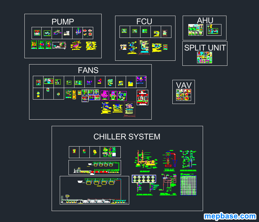
Every HVAC project, from a small commercial building to a university campus, lives or dies by its HVAC standard details. The floor plans tell you where equipment goes, but the standard details tell the contractor exactly how to install it: which valves go on a fan coil unit, how a chilled water pump sits on its inertia base, how an exhaust fan curb is flashed into the roof, and how a VAV box hangs from the slab.
In this guide, I’ve broken down a complete set of HVAC standard installation details taken from real approved shop drawings used on large-scale projects in Saudi Arabia and the Gulf region. If you’re an MEP engineer preparing shop drawings, a site engineer checking installations, or a draftsman building a CAD details library, this article walks you through every major detail category, what it must contain, and the mistakes consultants reject most often.
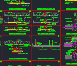
What’s in the Free DWG
The free DWG download includes the standard details covered in this guide:
- Fan coil unit hook-up, condensate trap and ceiling support details
- Floor-mounted and ceiling-suspended AHU details with piping isometric
- End suction pump, inertia base and plant room connection details
- Air-cooled chiller, absorption chiller and cooling tower piping details
- Roof extract fan curb, in-line fan and propeller fan details
- VAV box details (basic, reheat and fan-powered)
- DX refrigerant piping, split unit and roof penetration details
- Expansion tank, boiler and duct construction details
Looking for AHU and FCU installation sections with isometric views only? See our HVAC typical installation details DWG. For ready-to-insert diffusers, dampers and equipment blocks, get the HVAC dynamic blocks.
What Are HVAC Installation Details (and Why Consultants Insist on Them)?
HVAC installation details (also called typical details or standard details) are dimensioned, annotated drawings, usually drawn N.T.S. (Not To Scale), that show the standardized method of installing a piece of equipment or making a connection. A typical miscellaneous details sheet on a real project covers:
- Equipment hook-ups (fan coil units, AHUs, heat pumps, unit heaters)
- Pipework accessories and valve arrangements
- Vibration isolation, concrete pads and inertia bases
- Roof penetrations, curbs, flashing and waterproofing
- Duct construction, joints and flexible connections
- Controls and wiring interfaces (thermostats, DDC, BMS)
Consultants require them because a floor plan alone cannot enforce quality. A note like “install FCU as per detail” transfers a complete, pre-approved installation method to site, including strainers, balancing valves, drain traps and supports that would otherwise get “value-engineered” away.
1. Fan Coil Unit (FCU) Installation Details
Typical FCU Hook-Up Detail (Chilled & Hot Water)
The single most-used detail on any chilled water project is the typical FCU hook-up. A correct hook-up, reading from the supply pipe toward the coil, includes:
- Gate valve or ball valve (isolation) on both supply and return
- Y-strainer on the supply, upstream of the control valve, with a blow-off connection piped to drain
- 2-way motorized modulating control valve (or 3-way valve on constant-flow systems), with actuator accessible for maintenance
- Double regulating / balancing valve on the return (calibrated type with pressure test points for commissioning)
- Unions on both sides of the coil so the unit can be removed without cutting pipe
- Manual air vent at the coil high point and a 1/2″ gate valve (drain) at the low point
On real approved details, the accessories table even names the products: control valves by Siemens/Staefa (e.g., SQS65.5 actuators), clevis hangers to Grinnell Fig. 260, gate valves by Crane, and neoprene mounts by Mason. It is a good reminder that shop drawings should reference the approved material submittal, not generic symbols.
Condensate Drain Trap (Static Head Trap)
The most common site failure on FCUs is condensate overflow, and it almost always traces back to a missing or undersized drain trap. The standard detail requires:
- A U-bend trap at the drain pan outlet, where the trap depth X = negative internal static pressure at the fan inlet (draw-through units pull air backward through an untrapped drain)
- uPVC condensate pipe with a minimum fall of 1:100 toward the nearest drain point
- A tee with a cleanout plug for rodding
- Drain pipe insulation as per specification (to prevent sweating above false ceilings)
- A secondary drain pan in areas housing electrical materials
Ceiling-Mounted FCU Support
Concealed FCUs hang from the slab on threaded rods with rubber-in-shear or neoprene vibration isolators, washers and lock nuts. The detail also fixes the thermostat wiring: for a modulating system, the thermostat is suitable for 0–10 V DC output, the 2-way valve actuator is PID type, with separate wiring for 3-speed fan control, typically 6 hardwires between thermostat, valve and FCU.
2. Air Handling Unit (AHU) Installation Details
Floor-Mounted AHU on Concrete Pad
A typical floor-mounted AHU detail shows a concrete housekeeping pad (mechanical pad) with epoxy paint on top, steel U-channel edging, and the unit sitting on vibration isolators fixed with anchor bolts (e.g., Rawl SafetyPlus loose bolt M10×140, 15 mm drill). Sealant closes the gap between unit base and pad.
Ceiling-Suspended AHU Detail
Suspended units are carried on full-length supporting channels with elasto-rib pads the full width of the channel, hung on minimum 16 mm support rods secured to the building structure. Key annotations include minimum 200 mm clearance from air terminals to supports, a suspended access platform where required (coordinated with structural drawings), and a 20 mm unit drain terminated at the nearest drain.
AHU Piping Connection (Isometric Detail)
The chilled water connection to an AHU coil mirrors the FCU hook-up but at larger scale. The standard isometric legend runs through 14 items: union, 2-way motorized valve, tap and cock, thermometer well, stop cock, gate valve (double regulating), globe valve, strainer (connected to blow off to drain), flexible connection, vibration isolator, drain cock, automatic air vent with lockshield valve, concrete plinth, and filter manometer. Add a pressure gauge with cock and siphon across the coil, and a sound attenuator on the supply air side when the AHU has no internal space for it.
For a complete plant room layout, see our AHU plant room shop drawing.
Acoustical Duct Lining Detail
For AHUs and terminal units, the detail calls for 25 mm thick fiberglass acoustical duct lining, retained with galvanized channel (0.8 mm), applied for 10 m of supply and return duct length or up to the nearest branch, whichever comes first (4.5 m for terminal units, or to the nearest outlet).
3. Pump Installation Details (Chilled Water & End Suction)
End Suction Pump Detail
The classic end suction pump detail shows, on the suction side: gate valve, suction diffuser with strainer and blowdown valve, compound pressure gauge, and a flexible connector. On the discharge: check valve, balancing/plug cock valve, pressure gauge with gauge cock, concentric reducer, and a second flexible connector. The pump sits on a 6″ (150 mm) housekeeping pad, with the gland drip routed to the floor drain.
Inertia Base & Concrete Pad Detail
Chilled water pumps (CHWP-1 to CHWP-4 on a typical plant) are mounted on a concrete inertia base with spring isolators, framed in C-channel (100 mm), over the structural slab. The classic pad detail adds 50 mm cork (or 2 layers of 25 mm) under and around the foundation, side fill sealed with mastic, and bituminous compound on corner edges. The X and Y pad dimensions are sized to suit the pump channel base and the number of pumps. A site note that appears on real drawings: leave enough height above the strainer for basket removal.
Pump Connection Schematic
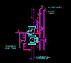
The plant room schematic ties the pumps to the air separator, diaphragm expansion tank, chemical feeder (pot feeder), automatic air vents on main headers and a 25 mm make-up connection, with a chemical treatment station (CHTS) whose controller sends an alarm to the BMS on loss of pH control.
4. Chiller Installation Details
Air-Cooled Chiller Piping Detail
The air-cooled chiller detail covers CHWS/CHWR connections with butterfly valves (slip-on steel flanges), flexible butyl rubber hose connections, thermometers, valved pressure gauges, a 20 mm blow-off valve connected to drain with air gap, large-capacity automatic air vent (minimum 1½”), machine base pad and pipe supports at roof FFL.
Steam Absorption Chiller (Single Effect)
Larger district-type plants include the steam absorption machine detail: generator, absorber, evaporator, condenser, low-temperature heat exchanger, refrigerant and absorbent pumps, with steam inlet/outlet through an F&T steam trap, chilled water in/out, and condenser water routed to the cooling tower. Steam supply gets a control valve, concentric reducer and globe valve arrangement.
Cooling Tower Piping Connections
The tower detail (single cell shown, typical) includes make-up water with float valve, sump with drain plug and anti-cavitation plate, continuous overflow pipe to drain, shut-off and flow-control valve with indicator at each tower inlet, and a 1″ (25 mm) inspection/test pipe with union, with a 12″ (300 mm) nipple removable between union and elbow. For multi-cell towers, the basins are interconnected by flumes, with one make-up, one overflow and one drain for the bank.
5. Fan Installation Details (Roof, In-Line & Propeller)
Roof Extract Fan & Curb Detail
The roof fan curb is where HVAC meets waterproofing, and where most leaks are born. The standard detail stacks: concrete curb (150 mm high min.) or prefabricated roof curb, 40×40 mm wood nailing strip all around, cant strip, roofing felt, counter-flashing, and the fan base screwed or bolted through a neoprene pad. Requirements that appear as notes on approved drawings:
- Secure the curb cap with 3/8″ (10 mm) cadmium-plated lag bolts at max 12″ (305 mm) centers
- Use expansion bolts on concrete roofs, rust-resistant bolts on metal deck / bar joist roofs
- Duct through the roof shall not exceed the curb size supplied with the hood
- Gravity backdraft damper on exhaust hoods, with bird screen on the discharge
- Provide a safety disconnect switch mounted under the motor dome for maintenance
In-Line / Axial Fan Installation
Axial and in-line fans hang on 10 mm minimum support rods with spring-type vibration isolator mounts, connected to duct via 150 mm flexible connections with companion flanges, and fitted with a gasketed access panel. The thrust restraint note matters for high-pressure systems: provide thrust restraints (Type “THR”) for axial flow fans above 4″ (100 mm) static pressure, attached symmetrically on both sides and adjusted to allow 1/4″ movement at start and stop.
Fan Inlet & Discharge Connections
Performance depends on geometry, not just fan selection. The connection detail ranks arrangements from best to fair and fixes the rules: transformation slope 1-in-7 preferred (1-in-4 permitted for low velocity), discharge elbow radius R1 ≥ 150 mm, square vaned elbows with take-offs opposite fan rotation, and 900 mm minimum clearance for access doors.
Wall-Mounted Propeller Fan
Propeller fans mount in a wooden frame with rubber seal, discharge grille with gravity shutters, and a guard, with a note that exhaust-duty fans shall not be fitted with filters.
6. VAV Box Installation Details
Basic VAV Terminal Unit
The VAV detail suspends the box on hanger rods (min 10 mm) from the structure, with a maximum 450 mm flexible duct on the primary air inlet (secured at both ends with draw bands), duct transitions to the box inlet/outlet, DDC control box access (allow at least 300 mm clearance to controls), digital thermostat located as shown or as approved, and a local fused or non-fused disconnect. Practical sizing notes: box height 350 mm max, width per unit capacity.
VAV with Reheat Coil
When a hot water reheat coil is added, the water side repeats the FCU logic: ball/gate isolation valves, calibrated balancing valve with pressure ports, 2-way (or 3-way modulating) control valve, unions, strainer with blow-off, manual air vents at all high points and 3/4″ drain valves with hose coupling at all low points, plus 1½” test wells for temperature and pressure test plugs.
Fan-Powered VAV Box
The fan-powered variant adds a secondary (plenum) air inlet with 1″ filter rack, an electric heater option with balancing taps, and the same primary-air flexible connection rules.
7. Split Units & DX Refrigerant Piping Details
Refrigerant Piping for DX Units
The refrigerant piping detail for a D-X air conditioning unit shows the full circuit: compressor, air-cooled condenser, receiver with safety relief valve, liquid line with stop valve, angle-type filter-drier (removable head), sight glass, solenoid valve and thermostatic expansion valve, thermal bulb on the suction line, and charging connections. Critical engineering notes carried on the drawing:
- Use a double suction riser where the suction line rises to the compressor on a system that runs at part load, so oil keeps returning at low capacity; the riser arrangement also changes depending on whether the DX coil sits above or below the compressor
- Duplicate the refrigerant piping for double-circuit systems
- Pipe sizes shown are based on R-22. Revise sizes if another refrigerant is used (essential today with R-410A/R-32 conversions)
- Field-installed refrigerant piping shall be approved by the equipment manufacturer
Wall/Ceiling-Mounted Split Unit Detail
The split unit detail coordinates three trades in one drawing: the outdoor condensing unit on a concrete base with anchor-bolted vibration isolators; refrigerant and drain pipes insulated with 19 mm polyurethane/rubber insulation plus fiberglass clothing and weatherproof coating; a 25 mm condensate drain to the nearest drain point; and the electrical interface, with a weatherproof IP-54 isolator (20A/30A DP as applicable), Kopex flexible connection, power and control wiring in G.I. conduit, and remote temperature controller at 1500 mm from FFL.
Refrigerant Pipes Through-Roof Detail
Roof penetrations for refrigerant pipes get their own detail: preformed 40×40 mm PVC upstand, flexible flashing fittings, mastic fill and seal around the copper pipes and control conduits. Never a bare core-drilled hole.
8. Expansion Tank, Boiler & Hydronic Accessories
Expansion Tank Installation Detail
The diaphragm-type expansion tank detail includes the safety valve piped to drain, gate valves, pressure gauge, quick-fill connection and solenoid on the filling line, connected at the system’s neutral point.
Hot Water Boiler Details
Cast iron and packaged hot water boiler details cover the burner (pressure-atomizing gun type or rotary cup), ASME relief valves discharging full-size to an open drain, combination low-water cut-off and emergency water feeder (set to operate at 25 mm above the top tube), separable-socket thermometers (30–240°F scale), flue/breeching to chimney, 100 mm concrete base and trough drain. Unit heater connections (horizontal and vertical) follow the standard supply/return valve-union-trap arrangement.
9. Duct Construction & Joints
The duct construction sheet standardizes longitudinal seams (grooved seam, spiral seam, butt-welded) and transverse joints (draw band with Acme lock, crimp joint 25 mm min, beaded sleeve, companion flange with angle rings and 6 mm bolts at 100 mm max spacing), built around a low-pressure galvanized steel ductwork specification table (duct construction schedule). Flexible ducts are limited (typically max 3 m on lined runs) and secured at both ends with draw bands; all ducts crossing fire-rated walls get fire dampers with the same time rating as the wall.
10. General Notes That Make or Break Approval
Beyond the graphics, real approved detail sheets carry general notes that consultants check line by line. From this drawing set, the ones every shop drawing should include:
- All outdoor equipment may be exposed to 110°F (43°C); motors and internal systems shall be IP 54 and operate without failure when outdoor temperature reaches 103°F (39.5°C), with indoor design/testing temperature of 74°F (23°C). Always check your own project specification, as many Saudi projects now specify an outdoor design temperature of 46°C or higher.
- The contractor shall obtain a manufacturer’s certification that equipment complies with the design; otherwise changes are at the contractor’s cost
- Locations of indoor units, grilles and inspection doors are coordinated with architectural drawings and approved by the architect
- Coordinate air intakes vertically to eliminate hot air recirculation
- Equipment models and dimensions are proposed only; final selection per approved submittals
- Contractor shall submit shop drawings finalizing details in coordination with equipment manufacturer recommendations
Quick Reference: HVAC Detail Checklist by Equipment
| Equipment | Must-Have Items in the Detail |
|---|---|
| FCU | Isolation valves, Y-strainer + blow-off, 2-way control valve, balancing valve, unions, air vent, drain valve, condensate U-trap (depth = fan static), 1:100 drain slope |
| AHU | Housekeeping pad, vibration isolators/anchor bolts, flexible duct connections, 14-item piping legend, pressure gauge with siphon, sound attenuator, drain trap |
| Pumps | Suction diffuser/strainer, check valve, flexible connectors, compound & discharge gauges, inertia base with spring isolators, cork-isolated pad |
| Chillers | Butterfly valves, flexible hoses, thermometers, blow-off to drain with air gap, auto air vent, base pad |
| Roof fans | Curb + wood nailer + flashing, backdraft damper, bird screen, disconnect switch, correct bolts for roof type |
| VAV boxes | Max 450 mm flex on primary inlet, 300 mm control access, hanger rods with isolation, reheat coil valve set, local disconnect |
| DX/Split | Filter-drier, sight glass, solenoid, TXV, double suction riser where needed, refrigerant-specific pipe sizing, insulated roof penetration |
How to Use These Details on Your Project
Standard details are a starting library, not a copy-paste job. Adapt each one to your project’s specification, approved materials and equipment submittals, then re-issue as project shop drawings with your own title block, drawing numbers and revision control. Pair them with correct equipment sizing: you can cross-check cooling loads with our AC Tonnage Calculator, verify coil and condensation conditions with the Dew Point Calculator, and size electrical feeds to HVAC equipment with the Electrical Panel Load Calculator.
Download HVAC Standard Details DWG
Get the complete set of HVAC standard details covered in this guide as one free AutoCAD file.
Checking…
Related Downloads
- HVAC Typical Installation Details DWG (Sections & Isometric)
- HVAC Dynamic Blocks with Equipment Installation Details
- AHU Plant Room Shop Drawing DWG
Frequently Asked Questions
What is the difference between HVAC typical details and shop drawings?
Typical details show the standardized installation method for a class of equipment (any FCU, any roof fan), while shop drawings apply those details to specific equipment, locations and dimensions on your project. Contractors adapt the consultant’s typical details into project shop drawings and submit them for approval.
Why does a fan coil unit need a condensate trap?
Draw-through units create negative pressure at the drain pan. Without a U-trap deep enough to overcome that negative static pressure, air is sucked backward through the drain and condensate overflows into the ceiling. The trap depth must equal or exceed the fan’s negative internal static pressure.
When are thrust restraints required on fans?
Many specifications, including the drawing set in this guide, require thrust restraints on axial flow fans and fan sections operating above 4 inches (100 mm) of static pressure. They are mounted symmetrically on both sides and adjusted to allow about 1/4″ (6–8 mm) of movement at start and stop. Always follow your project specification, as the threshold varies.
What is the maximum flexible duct length allowed to a VAV box or diffuser?
Standard details typically limit the flexible duct on a VAV primary air inlet to 450 mm maximum, secured at both ends with draw bands. Longer flexible runs (up to about 3 m) may be allowed only where specifically detailed, because flex duct adds significant pressure drop and sags easily.
Can I reuse R-22 refrigerant pipe sizes for R-410A systems?
No. Older standard details were sized for R-22 and carry an explicit note to revise pipe sizes if another refrigerant is used. R-410A and R-32 operate at different pressures and densities, so line sizes, oil return velocities and riser design must be recalculated per the manufacturer’s data.
Who is responsible for finalizing installation details on site?
The contractor. Approved detail sheets consistently note that the contractor shall submit shop drawings finalizing each detail in coordination with the equipment manufacturer’s recommendations, and shall obtain certification that the installed equipment complies with the design.