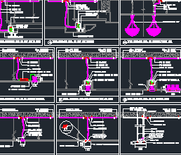
Cable Tray Installation Details DWG & PDF Free Download
Cable tray, cable ladder and trunking details are on almost every electrical shop drawing, and consultants check them closely: support spacing, earthing jumpers, expansion joints and fire barriers. This free package gives you a complete set of cable tray installation details in AutoCAD DWG and PDF, covering perforated cable tray, heavy-duty cable ladder, fittings, supports, underfloor and skirting trunking, and the typical installation details used on Gulf projects.
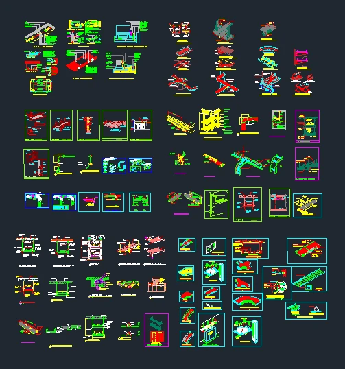
File details
| Item | Details |
|---|---|
| Format | AutoCAD DWG and a combined PDF |
| Sheets | 6 A0 detail sheets |
| Systems | Perforated cable tray, heavy-duty cable ladder, cable trunking (skirting, ceiling, underfloor, recessed), conduit |
| Content | Isometric fittings, support and fixing details, earthing, expansion joints, fire barriers and installation sections |
| Typical use | Electrical shop drawings, method statements and material submittals |
What’s inside the drawings
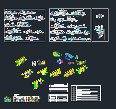
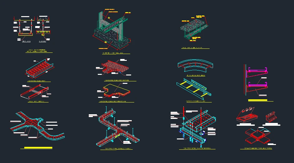
Cable tray and ladder isometric details
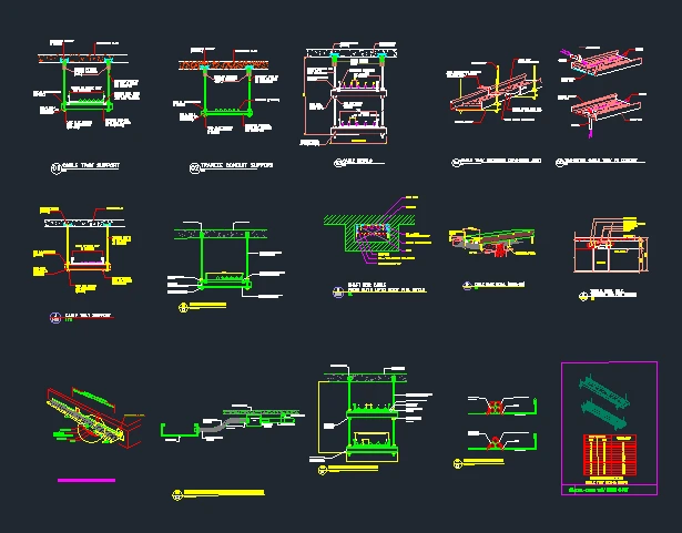
- Cable tray suspended from a concrete structure (front and side views), floor-mounted cable tray and ceiling support
- Perforated cable tray, tray coupling, tray branch and perforated tray with cover
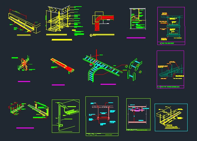
- 90° horizontal bend, heavy-duty cable ladder and wall-mounted cable ladder
- Cable ladder and cable tray typical installation details with reducing connectors, risers, tees and crosses
- Cable tray mechanical support system: threaded rod, slotted channel, flat plate fittings and fixings
- Underfloor trunking system: access box, 90° riser bend and junction unit
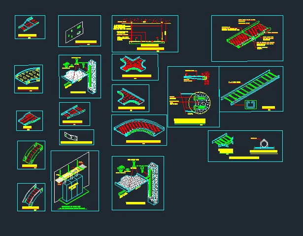
Cable tray fittings in 3D
- Left-hand and right-hand reducers, expansion connector and vertical adjustable connector
- 45° and 90° horizontal elbows, inside and outside 90° risers
- Horizontal tee and horizontal cross for cable tray and cable ladder
- Ceiling-mounted and wall-mounted (light duty) cable tray supports, and cables fixed on cable ladder
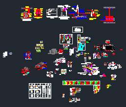
Supports, earthing and special details
- Cable tray support and trapeze conduit support from the slab
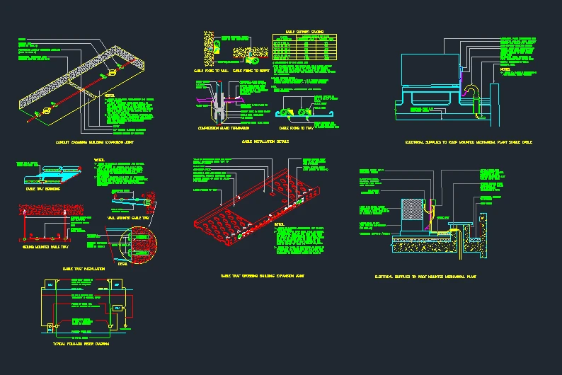
- Cable tray crossing a building expansion joint and transition from cable tray to conduit
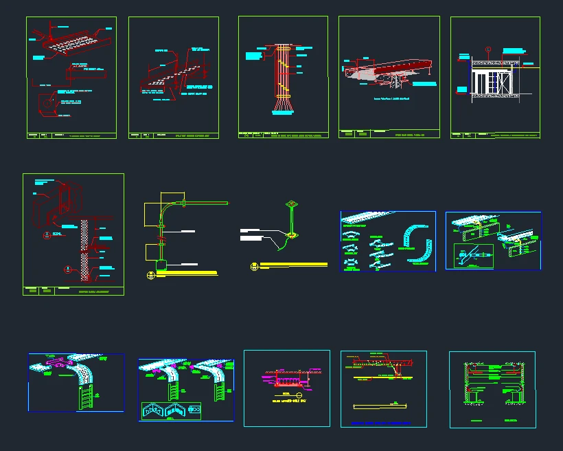
- Cable shaft detail from ground floor to roof and typical duct, tray, trunking and pipe section
- Detail of cable tray earthing and cable straps for single-core LV and MV cables
- Telecom cable tray sizing chart
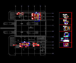
Trunking, conduit and building interfaces
- Cable tray wall support, ceiling support system and cable ladder support
- Cable tray fire barrier through walls and slabs, and roof-mounted cable tray with expansion upstand
- Three-compartment skirting and ceiling trunking, recessed trunking for security and communication systems, and the connection between trunking and a pull box
- Conduit crossing a building expansion joint, surface conduit mounting and raised floor pedestal grounding
- Cable installation details with a cable support spacing table, cable fixing to wall and soffit, and compression gland termination
- Electrical supplies to roof-mounted mechanical plant and a typical FCU riser diagram
Key installation rules shown in the details
| Item | Typical requirement |
|---|---|
| Support spacing | About 1.5 m for cable tray, unless the manufacturer’s load tables or obstructions require otherwise |
| Hangers | Threaded rod (M10 or 12 mm) with slotted channel 41 × 41 mm or 41 × 25 mm, hot-dip galvanized |
| Earthing | Flexible copper braid bonding jumpers across every joint and expansion connector; the tray is bonded to the earthing system |
| Expansion joints | Expansion connector where the tray crosses a building expansion joint, with a bonding jumper across the gap |
| Fire barriers | Penetrations through fire-rated walls and slabs sealed with a listed fire-stopping compound |
| Single-core cables | Laid in trefoil and held with cable straps or cleats so they stay put under short-circuit forces |
| Separation | Power and low-current cables in separate trays or separate trunking compartments |
Check how full a tray will be with the Cable Tray Fill Calculator and the Conduit Fill Calculator, size the cables with the Cable Size Calculator, and remember that cables grouped on a tray need grouping derating. Many specifications keep trays at about 40–50% fill to leave space for future cables.
Who this drawing is for
- Electrical draftsmen preparing shop drawings and installation details
- Site engineers checking cable tray and ladder installations
- MEP coordinators preparing material submittals and method statements
- Students and junior engineers learning how cable management systems are installed
How to use these details
- Download the DWG and open it in AutoCAD, or view the PDF. To preview the DWG without AutoCAD, use a free DWG file viewer.
- If text appears as boxes or question marks, install the missing AutoCAD SHX fonts.
- Copy the details you need into your detail sheet and update sizes, rod diameters and support spacing to the approved manufacturer’s catalogue.
- Add your project title block and reference the details from your cable tray layout drawings.
Download cable tray installation details
Checking…
More electrical details: Electrical Installation Detail DWG Library, AutoCAD Electrical Installation Details and Electrical Symbols and Installation Details DWG.
Frequently asked questions
What is the support spacing for cable tray?
About 1.5 m is a common maximum for cable tray supports, as noted in these details. Heavier cable loads, wider trays and the manufacturer’s load tables can require closer spacing, and supports are also placed near bends, tees and joints.
What is the difference between cable tray and cable ladder?
Cable tray has a perforated or solid base and suits smaller cables and mixed services. Cable ladder has two side rails joined by rungs, carries heavy power cables over longer spans, and lets the cables shed heat better.
How is cable tray earthed?
Each length is bonded to the next with a flexible copper braid jumper across every joint and expansion connector, and the tray system is connected to the main earthing system, so the tray is electrically continuous.
Why is an expansion connector needed?
Where a tray crosses a building expansion joint, or on long straight runs, an expansion connector lets the tray move without buckling. A bonding jumper keeps the earth continuity across the gap.
Can I use these details for my project?
Yes, as a reference and starting point. Adjust sizes, fixings and support spacing to the approved manufacturer’s products, the project specification and local regulations before submission.