Refrigerant Pipe Sizing for VRF and Split Systems: Step-by-Step Guide
Undersized refrigerant lines cost capacity; oversized suction risers leave oil stranded in the pipe and starve the compressor. This guide walks through refrigerant pipe sizing step by step for split and VRF systems: the design limits, typical line sizes, VRF branch layout, length and height checks, and additional refrigerant charge, with a full worked example.
Why refrigerant piping is different
Water pipes and air ducts only have to carry a single-phase fluid at a reasonable pressure drop. Refrigerant lines carry refrigerant in different states and also have to bring compressor oil back with it. A split or VRF system has two main lines:
- Liquid line: high-pressure liquid from the outdoor unit to the indoor unit’s expansion device.
- Suction (gas) line: low-pressure vapour from the indoor unit back to the compressor. This is the larger pipe and the one most affected by pressure drop and oil return.
- Heat recovery VRF systems add a third pipe (high-pressure gas or discharge line) so some indoor units can heat while others cool.
Step 1: Understand the three design limits
Every line size is a balance between three limits:
- Pressure drop. Friction in the suction line lowers the saturation temperature at the compressor and reduces capacity. A common target is a loss equivalent to about 1 K (2°F) of saturation temperature per line.
- Oil return. Oil leaves the compressor with the refrigerant and must be carried back. In suction risers, where gas flows upward, velocity must stay high enough to lift the oil.
- Velocity and noise. Liquid lines are kept slow to avoid liquid hammer and noise; gas lines are capped to avoid noise and excessive pressure drop.
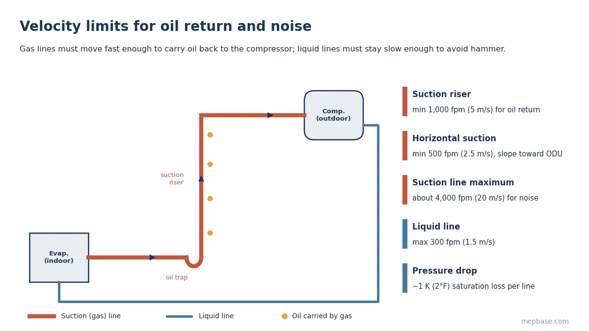
These limits pull in opposite directions. A larger suction pipe lowers pressure drop but also lowers velocity, so a pipe that is fine horizontally may fail to return oil in a riser. That is why suction risers are sometimes one size smaller than the horizontal line feeding them.
Step 2: Size split system lines by capacity
For single split and ducted split units, manufacturers publish fixed connection sizes based on unit capacity. Typical sizes for R-410A and R-32 units:
| Unit capacity | Liquid line | Suction (gas) line |
|---|---|---|
| 1 TR (12,000 Btu/h, 3.5 kW) | 1/4 in (6.4 mm) | 3/8 to 1/2 in (9.5 to 12.7 mm) |
| 1.5 TR (18,000 Btu/h, 5.3 kW) | 1/4 in (6.4 mm) | 1/2 in (12.7 mm) |
| 2 TR (24,000 Btu/h, 7.0 kW) | 3/8 in (9.5 mm) | 5/8 in (15.9 mm) |
| 3 TR (36,000 Btu/h, 10.5 kW) | 3/8 in (9.5 mm) | 3/4 in (19.1 mm) |
| 4 to 5 TR (48,000 to 60,000 Btu/h, 14 to 17.5 kW) | 3/8 in (9.5 mm) | 7/8 in (22.2 mm) |
These are typical values only. Always use the sizes in the unit’s installation manual, especially for long runs where the manufacturer may require a larger suction line on horizontal sections. If you are still working out unit capacity, start with the HVAC Load Calculation Guide or the AC Tonnage Calculator.
Step 3: Size VRF main pipes and branches
A VRF system connects one outdoor unit (ODU) to many indoor units (IDUs) through a tree of pipes and branch joints (often called refnet joints or Y-branches). Sizing follows a simple rule set:
- The main pipe from the ODU to the first branch joint is sized on the outdoor unit capacity.
- Each pipe between branch joints is sized on the total capacity of the indoor units downstream of it.
- Each branch pipe to an indoor unit matches that unit’s connection sizes.
- Each branch joint is selected from the manufacturer’s table using the total downstream capacity.
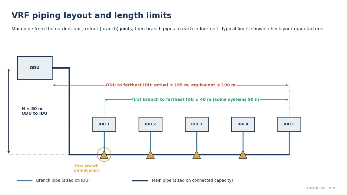
Branch joints must be installed in the orientation the manufacturer allows (usually horizontal or vertical, never tilted), with a minimum straight length after each joint before the next fitting, commonly around 0.5 m.
Step 4: Check length and height limits
VRF systems have hard limits on pipe length and height difference. The exact numbers depend on the manufacturer and model; these ranges are typical:
| Check | Typical limit |
|---|---|
| ODU to farthest IDU, actual length | 120 to 165 m (390 to 540 ft) |
| ODU to farthest IDU, equivalent length | 150 to 190 m (490 to 620 ft) |
| Total piping length (all pipes) | 500 to 1,000 m |
| First branch joint to farthest IDU | 40 m, extendable to 90 m on some systems with conditions |
| Height difference, ODU above IDU | 50 m (164 ft) |
| Height difference, ODU below IDU | 40 m (131 ft) |
| Height difference between IDUs | 15 to 30 m (49 to 98 ft) |
Equivalent length adds an allowance for each elbow, branch joint and oil trap to the actual length. Use the manufacturer’s equivalent lengths for fittings; for preliminary checks, an allowance of 15 to 25% of actual length is a reasonable starting point.
Step 5: Calculate the additional refrigerant charge
Outdoor units are factory-charged for a short piping run. The site adds refrigerant based on the length and size of the liquid line, because that is where most of the refrigerant mass sits:
Additional charge (kg) = Σ (liquid line length (m) × charge per metre for that size)
| Liquid line size | Typical charge for R-410A (kg/m) | (lb/ft) |
|---|---|---|
| 6.4 mm (1/4 in) | 0.022 | 0.015 |
| 9.5 mm (3/8 in) | 0.059 | 0.040 |
| 12.7 mm (1/2 in) | 0.12 | 0.081 |
| 15.9 mm (5/8 in) | 0.18 | 0.121 |
| 19.1 mm (3/4 in) | 0.26 | 0.175 |
| 22.2 mm (7/8 in) | 0.37 | 0.249 |
Charge factors differ between manufacturers and refrigerants, and some systems also add a fixed amount per outdoor or indoor unit. Use the values in your installation manual and record the final charge on the unit nameplate.
Refrigerant pipe sizing: worked example for a 56 kW VRF system
A 56 kW (20 HP) R-410A VRF outdoor unit on the roof serves eight ceiling cassette units on the two floors below. From the manufacturer’s tables, the main pipe is 28.6 mm (1-1/8 in) gas and 15.9 mm (5/8 in) liquid. The layout gives these lengths and heights:
| Check | Design value | Typical limit | Result |
|---|---|---|---|
| ODU to farthest IDU, actual | 85 m | 165 m | OK |
| ODU to farthest IDU, equivalent | 85 + 15 (fittings) = 100 m | 190 m | OK |
| First branch to farthest IDU | 35 m | 40 m | OK |
| Height, ODU above IDUs | 25 m | 50 m | OK |
| Height between IDUs | 4 m | 15 m | OK |
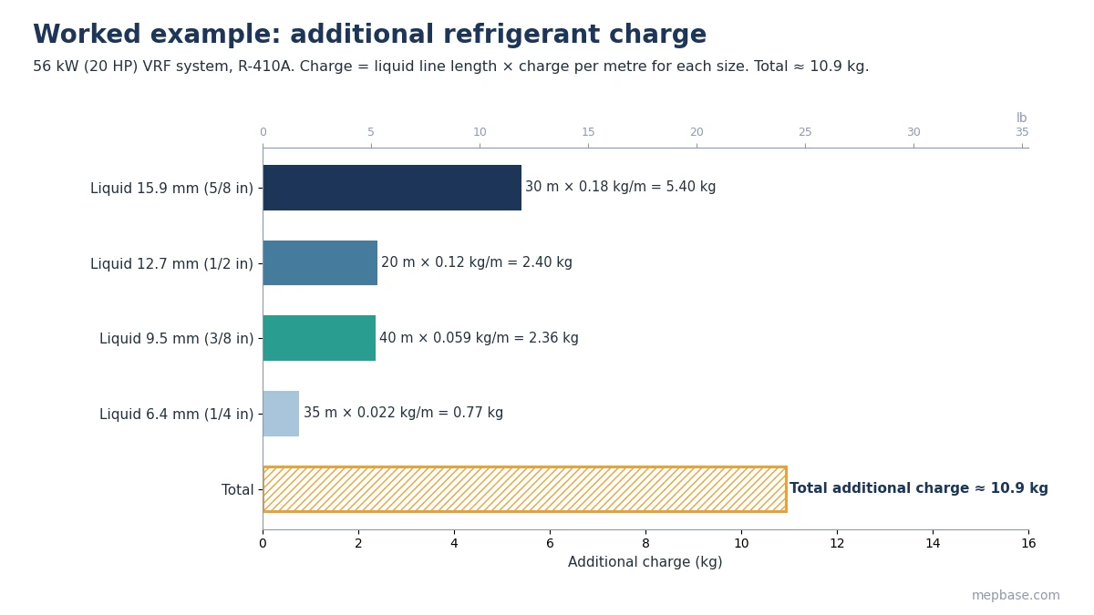
Additional charge from the liquid line lengths:
| Liquid line | Length | Charge per metre | Charge |
|---|---|---|---|
| 15.9 mm (5/8 in) | 30 m | 0.18 kg/m | 5.40 kg |
| 12.7 mm (1/2 in) | 20 m | 0.12 kg/m | 2.40 kg |
| 9.5 mm (3/8 in) | 40 m | 0.059 kg/m | 2.36 kg |
| 6.4 mm (1/4 in) | 35 m | 0.022 kg/m | 0.77 kg |
| Total additional charge | 10.9 kg (24 lb) |
Check your own line sizes and velocities with the Refrigeration Pipe Sizer, and convert between metric and imperial pipe sizes with the MM to Inches Converter.
Pipe material and installation notes
- Use clean, dehydrated ACR copper pipe (to ASTM B280 or EN 12735-1) with the wall thickness the manufacturer specifies. R-410A and R-32 run at higher pressures than older refrigerants, so larger sizes are often hard-drawn.
- Braze with dry nitrogen flowing through the pipe to prevent oxide scale forming inside.
- Pressure test with dry nitrogen at the manufacturer’s test pressure, then evacuate to 500 microns or lower before charging.
- Insulate the liquid and gas lines separately with closed-cell insulation of the thickness required for the site humidity.
- Support pipes so the weight never sits on the branch joints or unit connections.
For typical installation drawings, see HVAC Installation Details.
Common mistakes
- Upsizing a suction riser to reduce pressure drop, which drops velocity below what is needed to return oil.
- Using the actual length instead of equivalent length when checking VRF limits.
- Tilting branch joints or fitting an elbow straight after a joint, which upsets refrigerant distribution.
- Charging by guesswork instead of calculating additional charge from liquid line lengths.
- Brazing without nitrogen, leaving oxide flakes that block expansion valves and filters.
Frequently asked questions
How do I size refrigerant pipe for a split AC?
Use the liquid and suction line sizes in the unit’s installation manual. They are fixed by capacity, for example 1/4 in liquid and 1/2 in suction for many 1.5 TR units.
What is the maximum refrigerant pipe length for VRF?
Typically 120 to 165 m actual and 150 to 190 m equivalent from the outdoor unit to the farthest indoor unit, depending on the manufacturer and model.
Why does a suction riser need a minimum velocity?
Oil travels with the refrigerant. In a riser, gas must move fast enough, around 1,000 fpm (5 m/s), to carry the oil up and back to the compressor.
How is additional refrigerant charge calculated?
Multiply each liquid line length by the manufacturer’s charge per metre for that size, then add the results together.